 Nick Ames
An electrophoretic (e-ink) display requires a bunch of different power supply voltages. There are a few off-the-shelf chips (such as the TI TPS65185) which can provide all of them, but they're physically too large. (To maintain flexibility, I'd like for each component to be less than 3mm wide.) As a result, the supplies must be generated by separate regulators. Selecting these regulators is a challenge, since they must be physically small while consuming very little power.
Overall, the system requires seven voltage rails:
| Voltage | IC | Purpose |
| 1.8V | TI TPS62746 | Microcontroller/Bluetooth/Misc |
| 3.3V | AD ADP160ACBZ | Display/Pulse Sensor |
| 15V | LT LT8410 | Display |
| 25V | LT LT8410 | Display |
| -15V | LT LT3483 | Display |
| -32V | LT LT3483 | Display |
| VCOM (adjustable) | LT LT6003 | Display |
System power is provided by a 0.5mm thick 40mAhr li-ion battery (single cell; 3.5-4.2V). (The TI BQ29700DSER is used for battery under-voltage protection.) The 1.8V regulator runs continuously. All the other supplies are controlled by the microcontroller, to be enabled only when needed.
I made a PCB to characterize and test each regulator:

At the top are jumpers that select the current measurement resistor in series with each regulator circuit. Output voltages are measured on the bottom. The female headers are for plugging in resistors, for load testing. The jumpers to the side of each supply enable or disable it. (Since the 1.8V supply is always running, it's jumper controls the battery voltage measurement divider switch, a useful feature.)
Here's a photo of the test setup. To the right, not shown, is a 5.5 digit bench multimeter (a Fluke 8520A) for current and voltage measurements. It can provide .1uA current resolution using the 10 ohm sense resistors. The breadboard to the left generates a 1.8V rising edge from a button press.
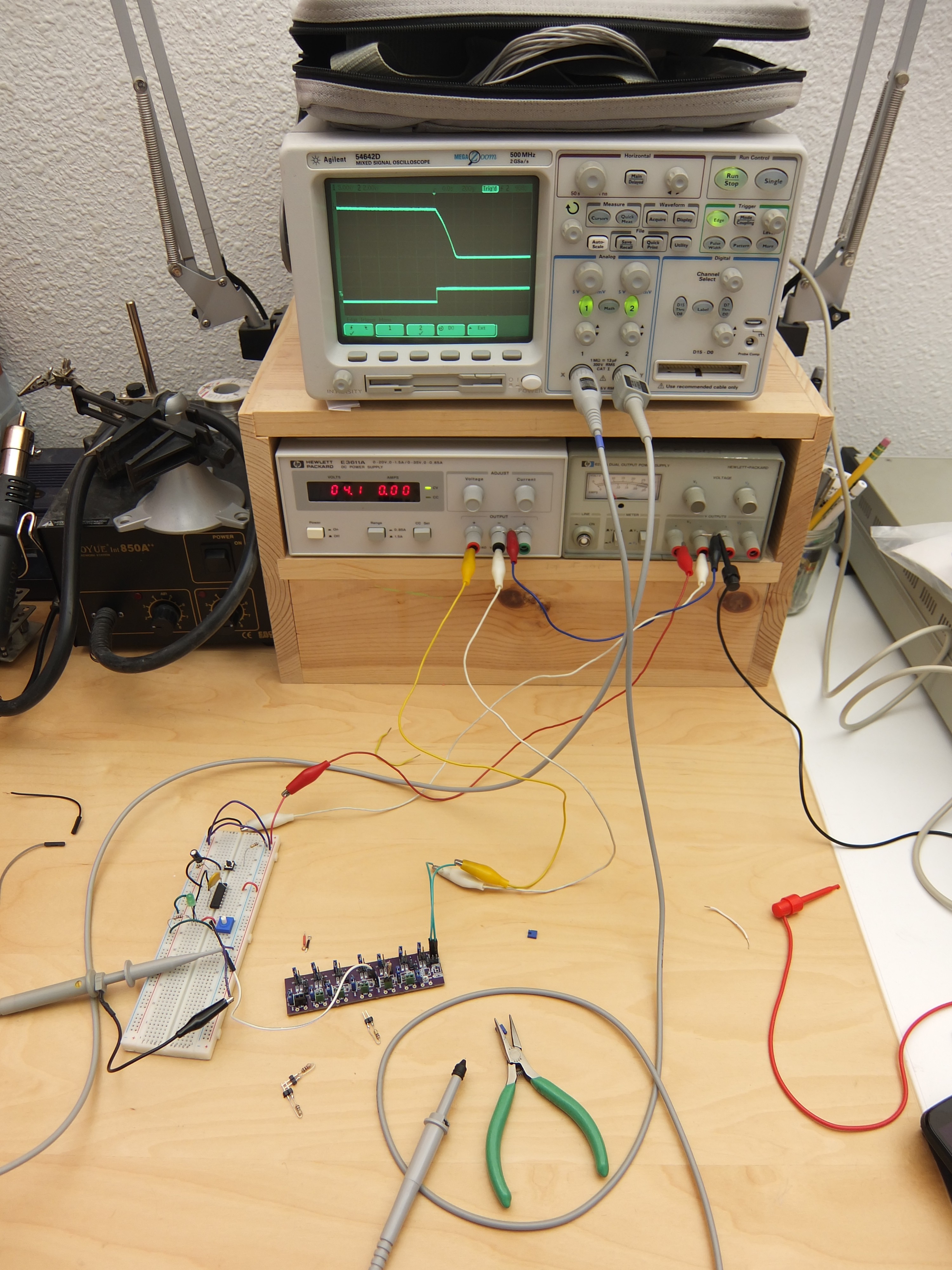
Overall, the test results were satisfactory. The 1.8V regulator slightly exceeded its astonishing 460na quiescent current spec, consuming 600nA, which is still very impressive. The 15V, 25V, -15V, and 32V regulators didn't fair so well. They consumed substantially more than their datasheet specified. However, each was still under 200uA quiescent, so I'm not worried about it. These supplies will only be enabled when the display is updating, and its power draw will be substantially larger.
For the full details, take a look at the Power Supplies Test Data spreadsheet in the files.
Discussions
Become a Hackaday.io Member
Create an account to leave a comment. Already have an account? Log In.
Is this project still happening? Did you hit a roadblock?
Are you sure? yes | no
Wow
Are you sure? yes | no
Hey,
I'd like to take a look at your spreadsheet, but the file extension seems to be missing. Excel won't open it. What kind of file is it?
Are you sure? yes | no
It was an ODF file. I uploaded a new version in XLS format, with an extension.
Are you sure? yes | no