 oakkar7
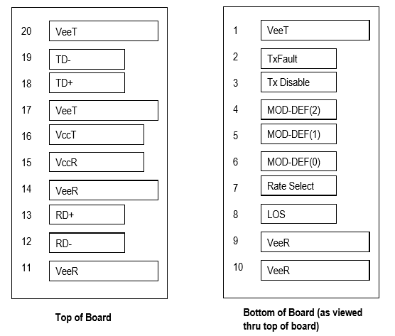
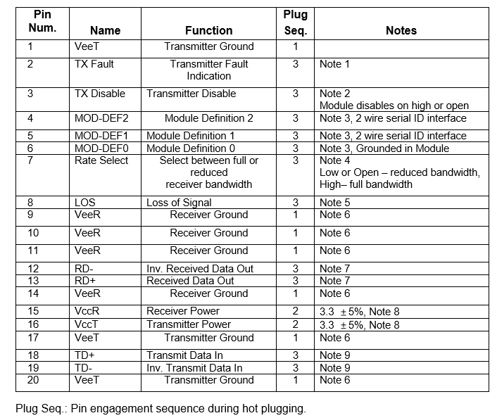
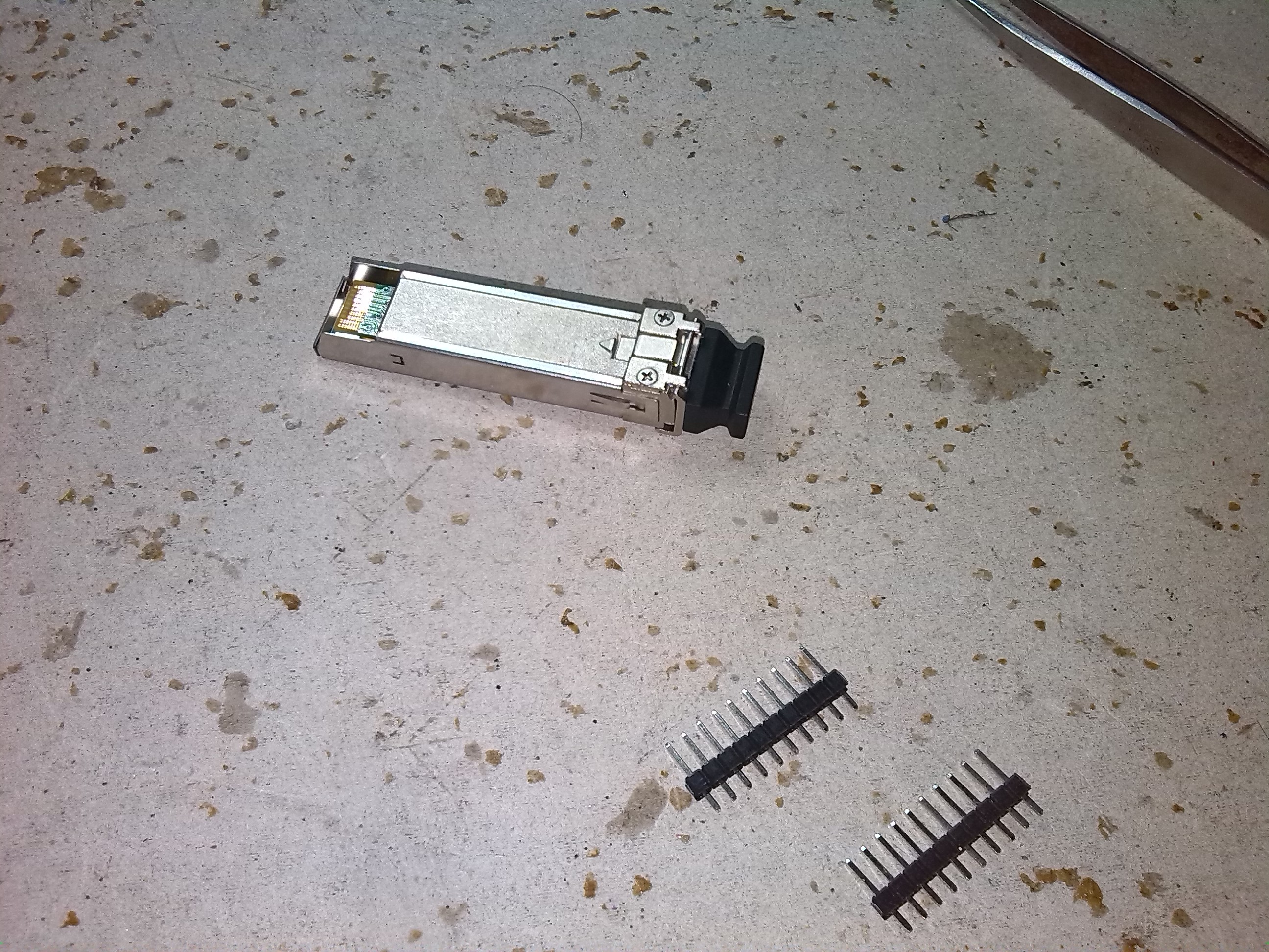
The first and tricky step is to solder SFP modules. The module pin outs is as follows. I need to solder 20 connectors with 20 wires to a standard 1.5mm pin outs. I used Mikrotik S-31DLC20D, a 1.25G SFP transceiver with a 1310nm Dual LC connector, for up to 20 kilometer Single Mode fiber connections, with DDM. But you may use any SFP module without problem.
Another reason I used Dual connector (TX and RX are different fiber interfaces) is to control TX function as additional. Thus, meter can transmit laser source and enable and disable this.
A good ref for SFP modules pin outs from finisar is here:
https://www.finisar.com/optical-transceivers/ftlf1318p3btl
1) Standard SFP pinouts is as follows.
2) Soldering and result is as follow. We can omitted Data TX/RX pair pins for now.
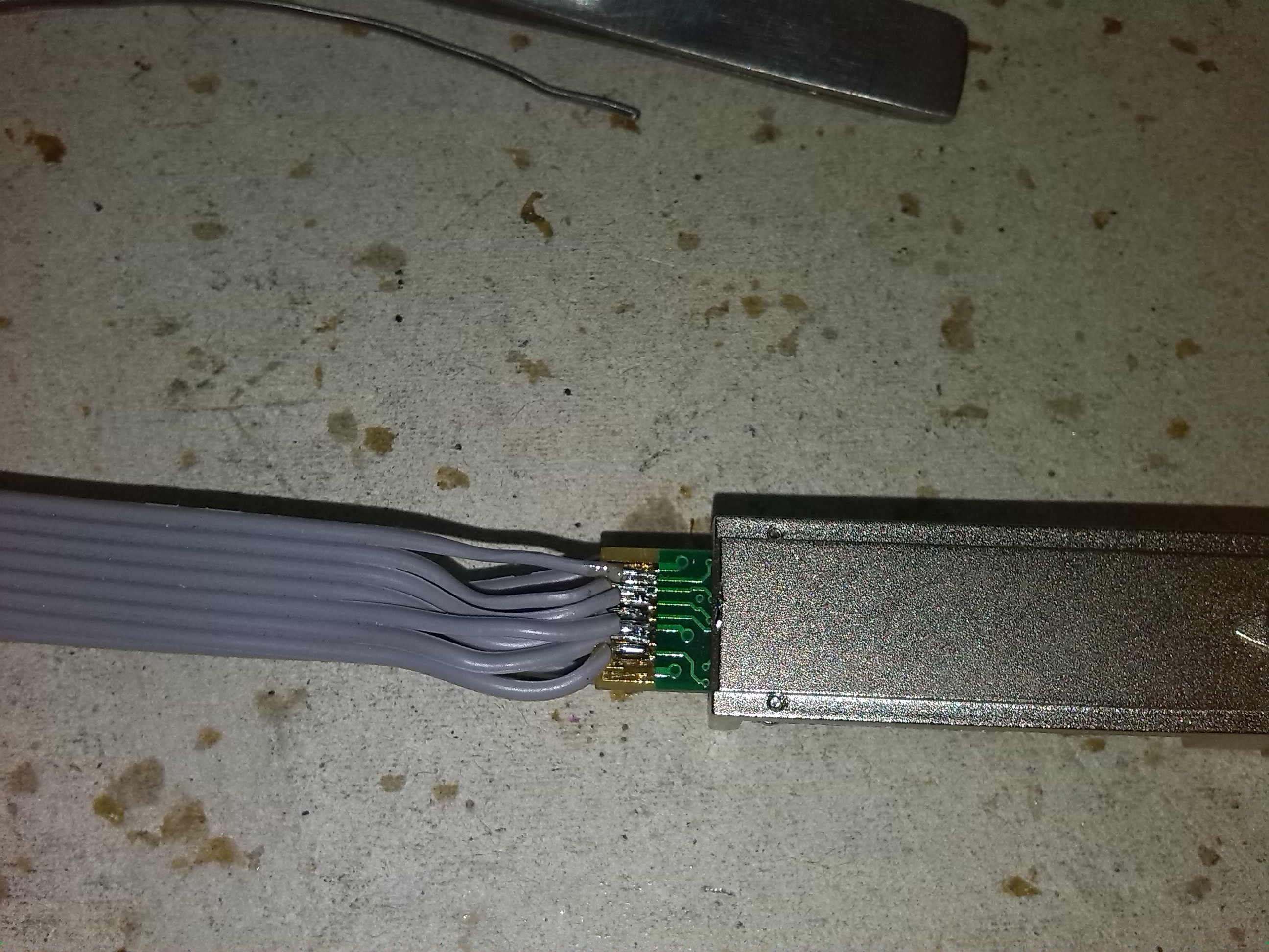
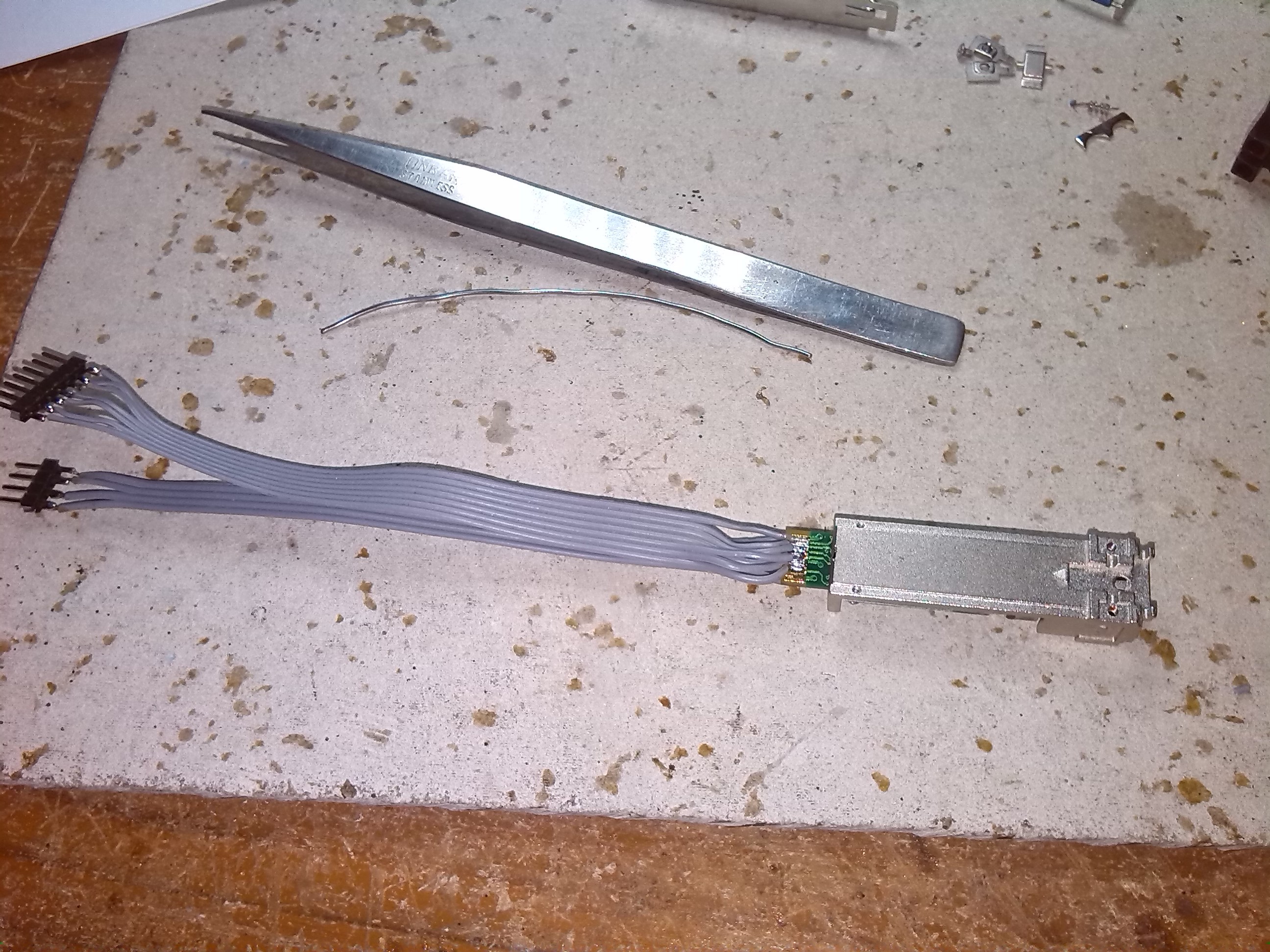
Next is interfacing with Arduino
Discussions
Become a Hackaday.io Member
Create an account to leave a comment. Already have an account? Log In.
SFP can module only work at 1310 nm. Or can you change the wavelength, for example at 1550 nm?
Are you sure? yes | no
maybe its too late but normally the sfp's modules are all different between each other's. When you buy them you need to make sure the module does/have what you need it to do. For example, some modules only support one or two wavelengths, other can support more than that, there are modules for everything you can imagine.
Are you sure? yes | no