-
Phase-5# Final Touch
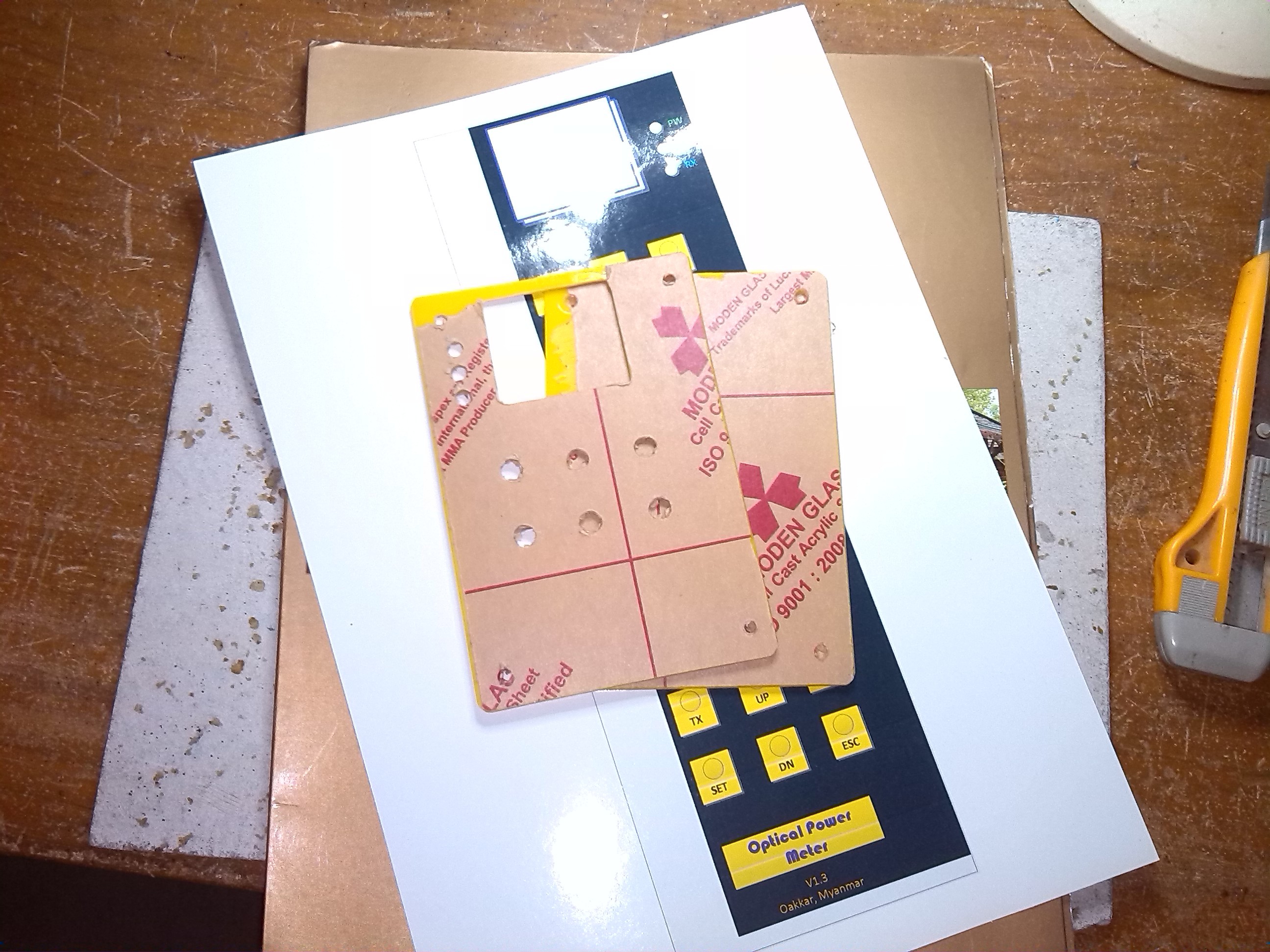
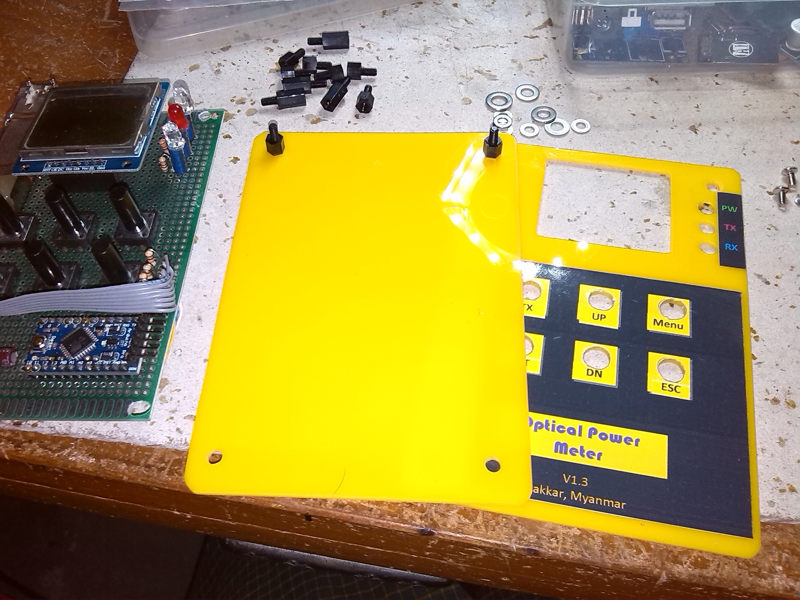
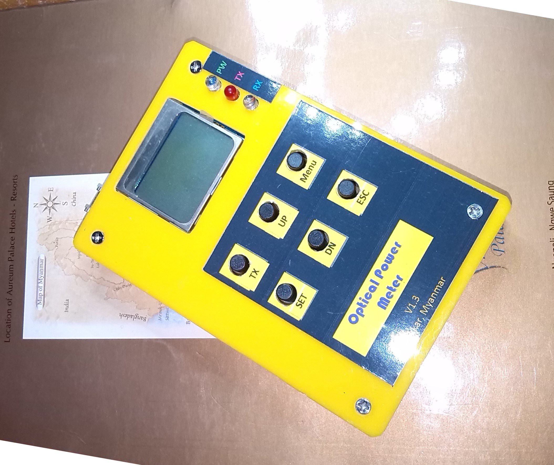
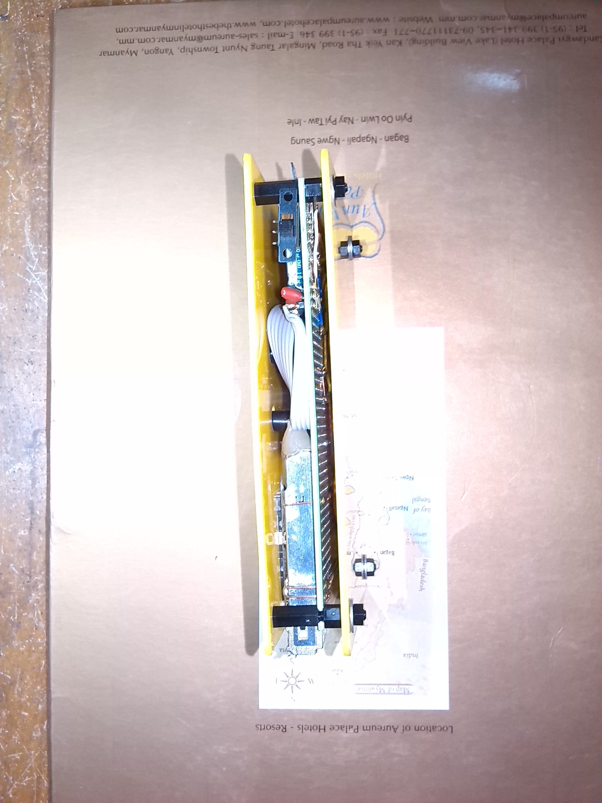
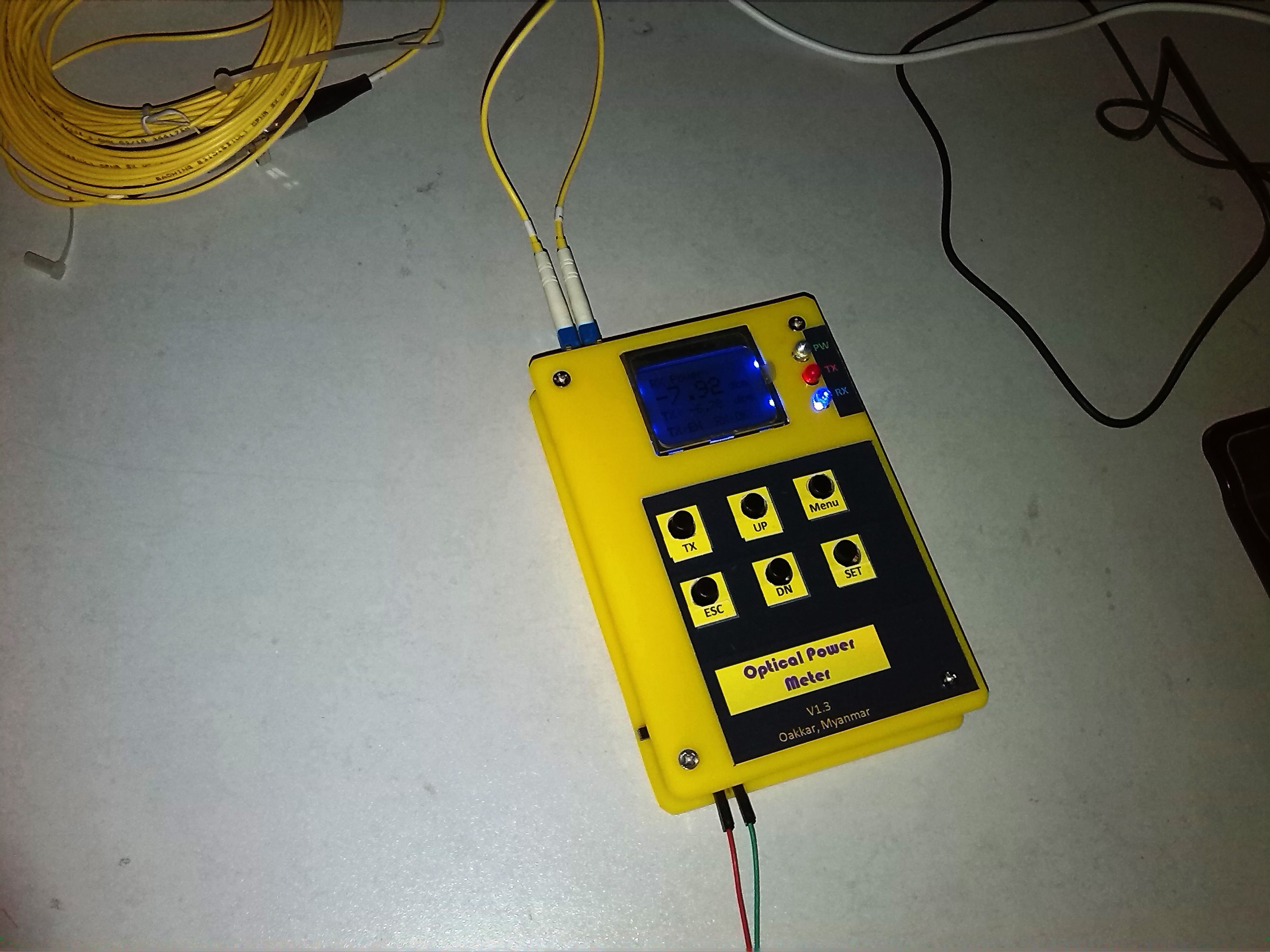
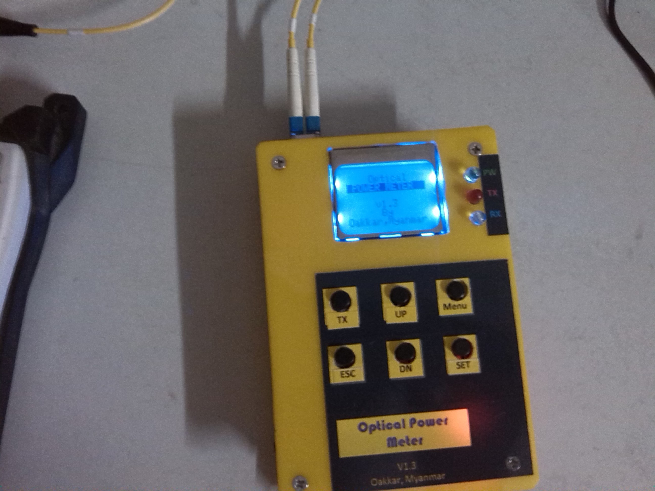
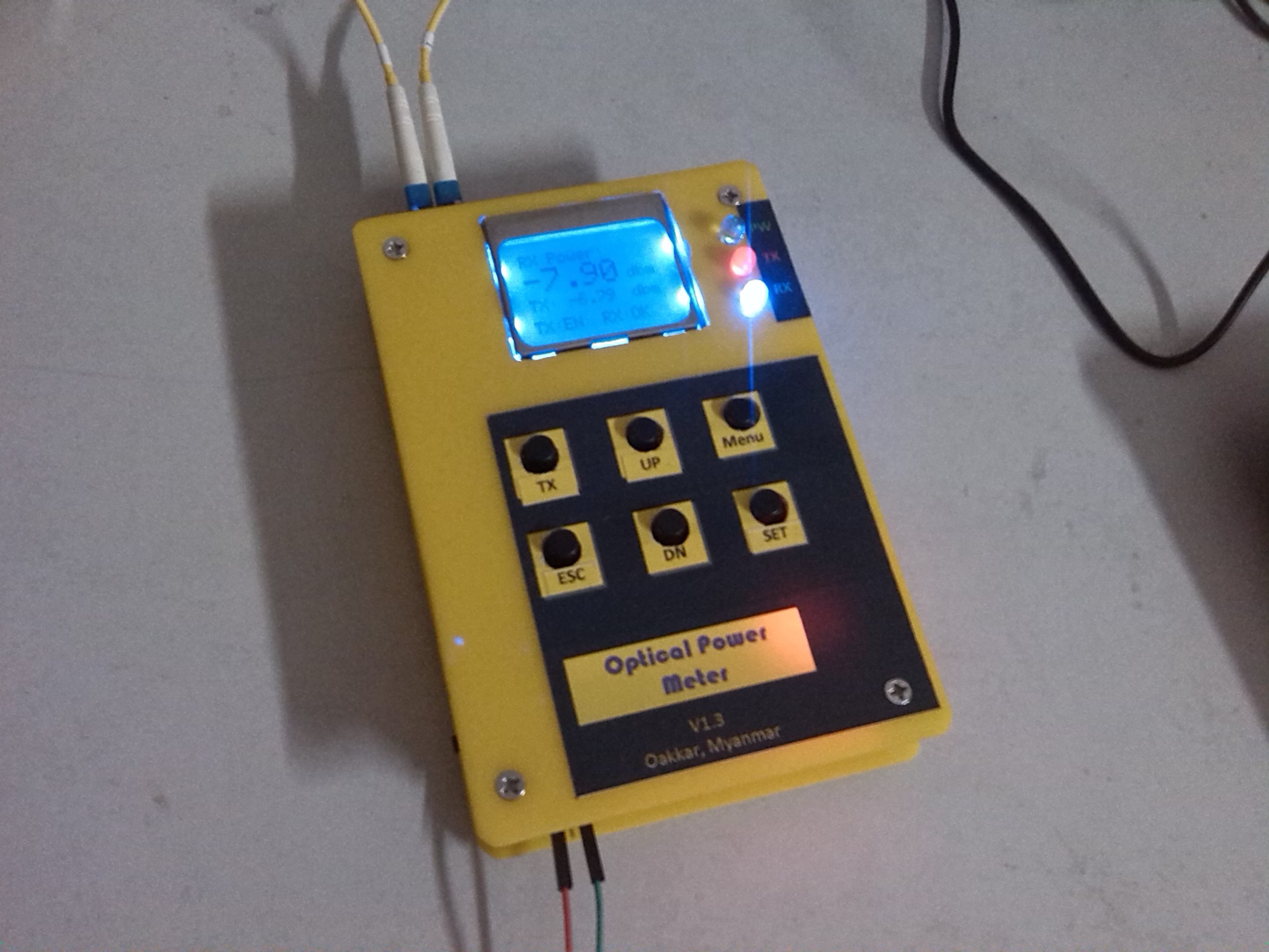
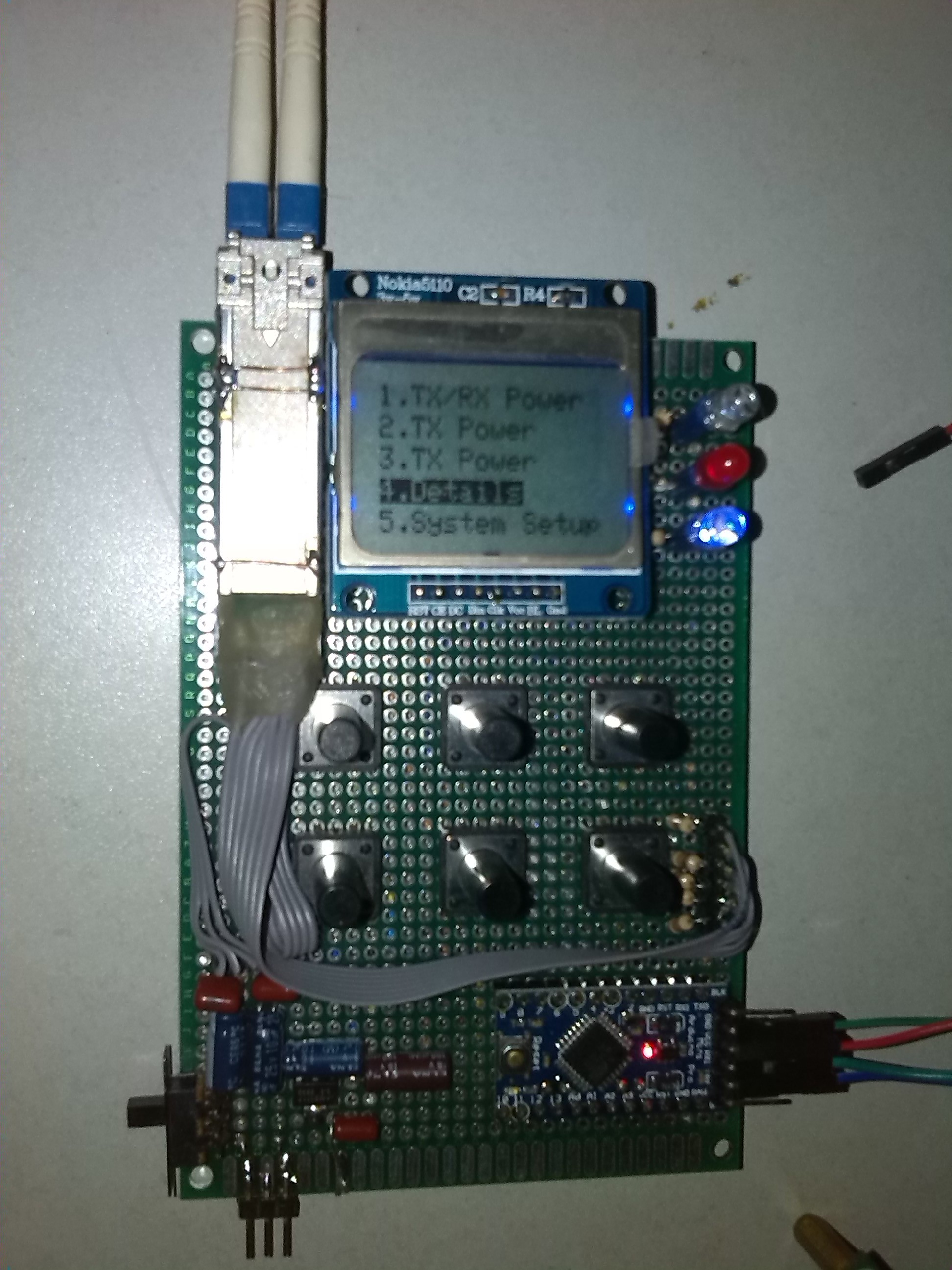
07/09/2017 at 15:48 • 0 commentsPrepare cover template with visio and hand cut Sandwich chassis by acrylic sheet. Installed the cover and tested for final result.
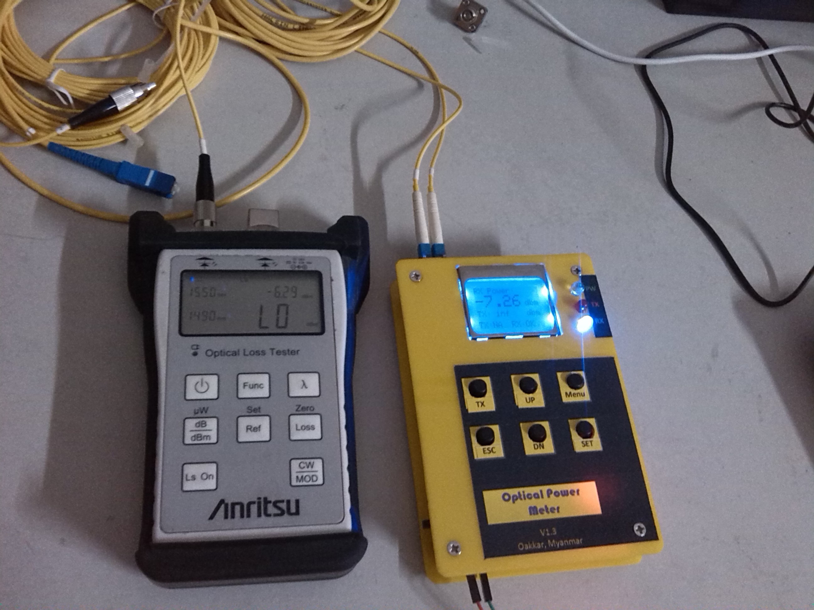
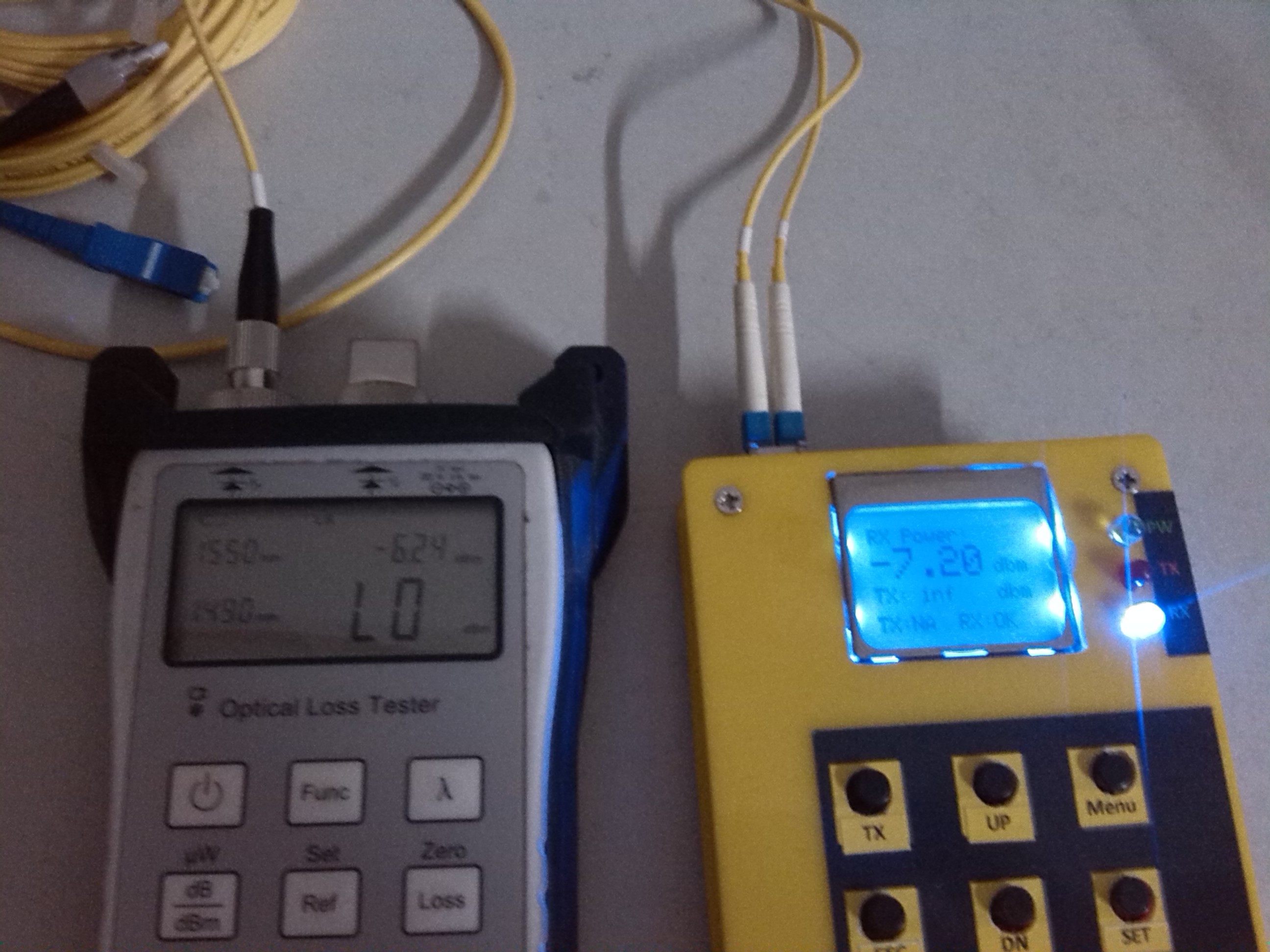
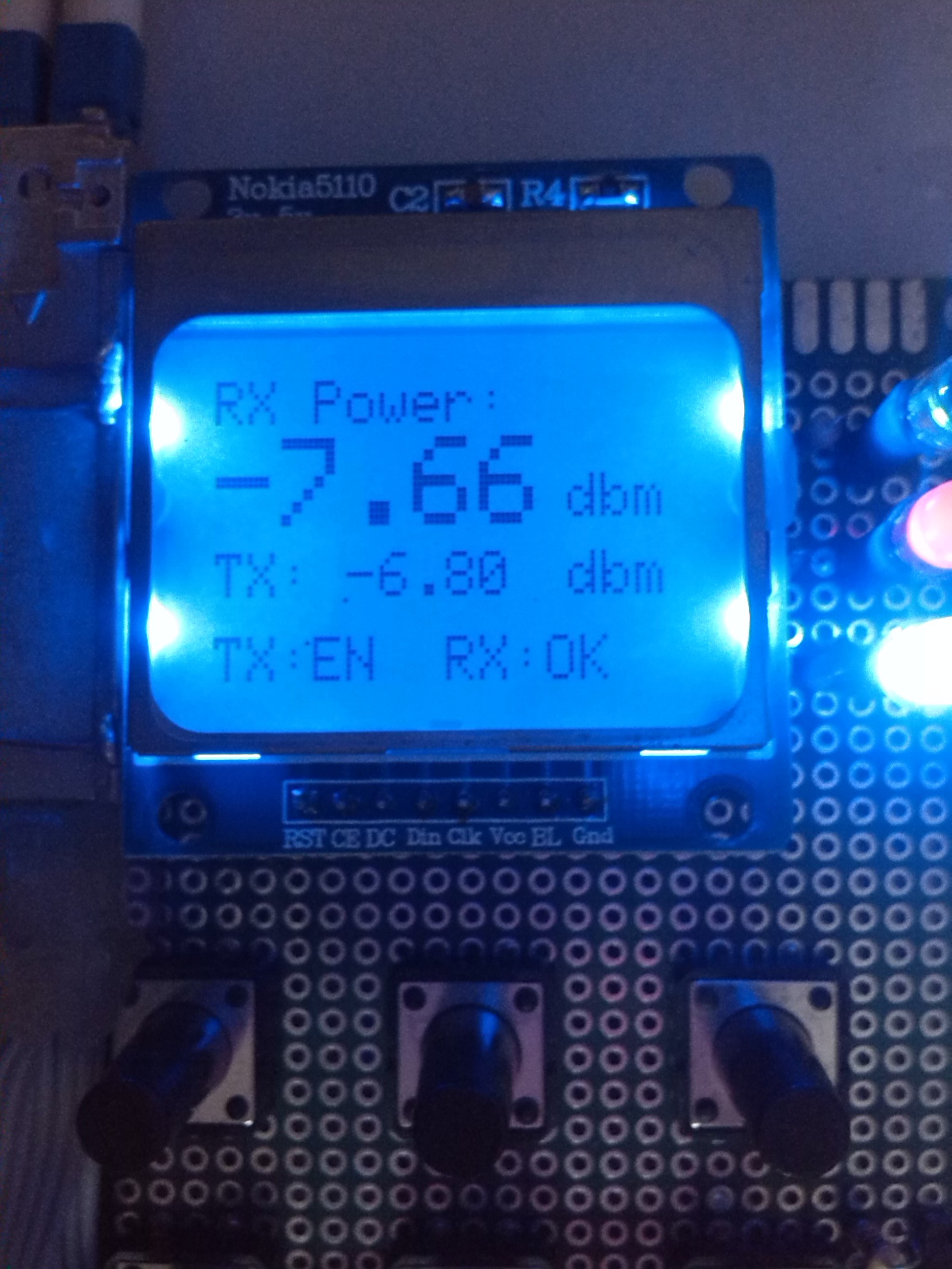
Finally, tested and calibrated with commercial optical power meter. The reference model is Anritsu, SLT35-FU. The test result show that build meter is +/- 0.03 dbm accuracy. Anyway, it is the best result for DIY optical fiber telecommunication test device.
Cheers,
Oak Kar
MYANMAR
1- Cover template and hand cut acrylic plates.
![]()
2- installed M3 plastic footing nuts.
![]()
3- Assembled.
![]()
![]()
4- Power up.
![]()
![]()
![]()
5-Calibrated with commercial Anritsu power meter.
![]()
![]()
that all :D
-
Phase4# Building Hardware
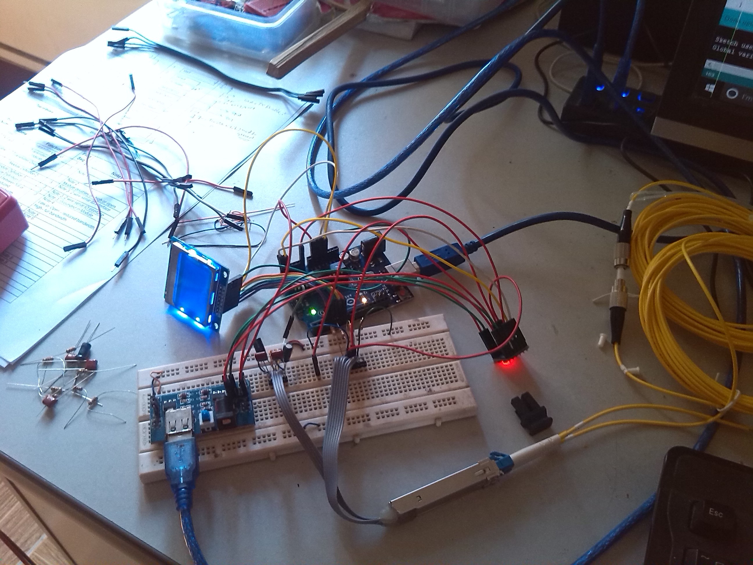
05/01/2017 at 05:59 • 0 commentsNext part is to build working prototype. I choose Arduino Pro Mini for some reasons, its compact and cheap, more IO than normal UNO board. And it can be run with 3.3V and not need level shifter for SFP interface.
There are some limitations in Arduino Pro Mini. I realize that pin count is not enough for my requirements. I need 6 x GPIO pins for 6 push button switches. After using 10 pins for SFP and 5 Pins for LCD, 3 pins for LEDs, there is not much pins left for switches.
1) issues and workarround
Analog pin 6 and 7 are analog only input pins. Problem is these two pins not work reading as digital IO. After using mu GFu, someone shows the trick to use analog only pins as digital I/O. Here is code snip.
EN_sw = analogRead(A7) > 256 ? 0 : 1;2) UART debug
For debugging and future extension such as PC or phone application interfacing, I added debug function in lib.
3) Menu
There are 6 Switches and main menu + sub-menu system in system.
- Splash Page
- About Page
- Main Menu
- TX/RX Sub-menu
- TX Sub-Menu
- RX Sub-Menu
- Detailed
- System Setup Sub-Menu
Key functions are as follows.
TX ENABLE/DISABLE UP Function CLEAR DOWN SET 4) Schematic
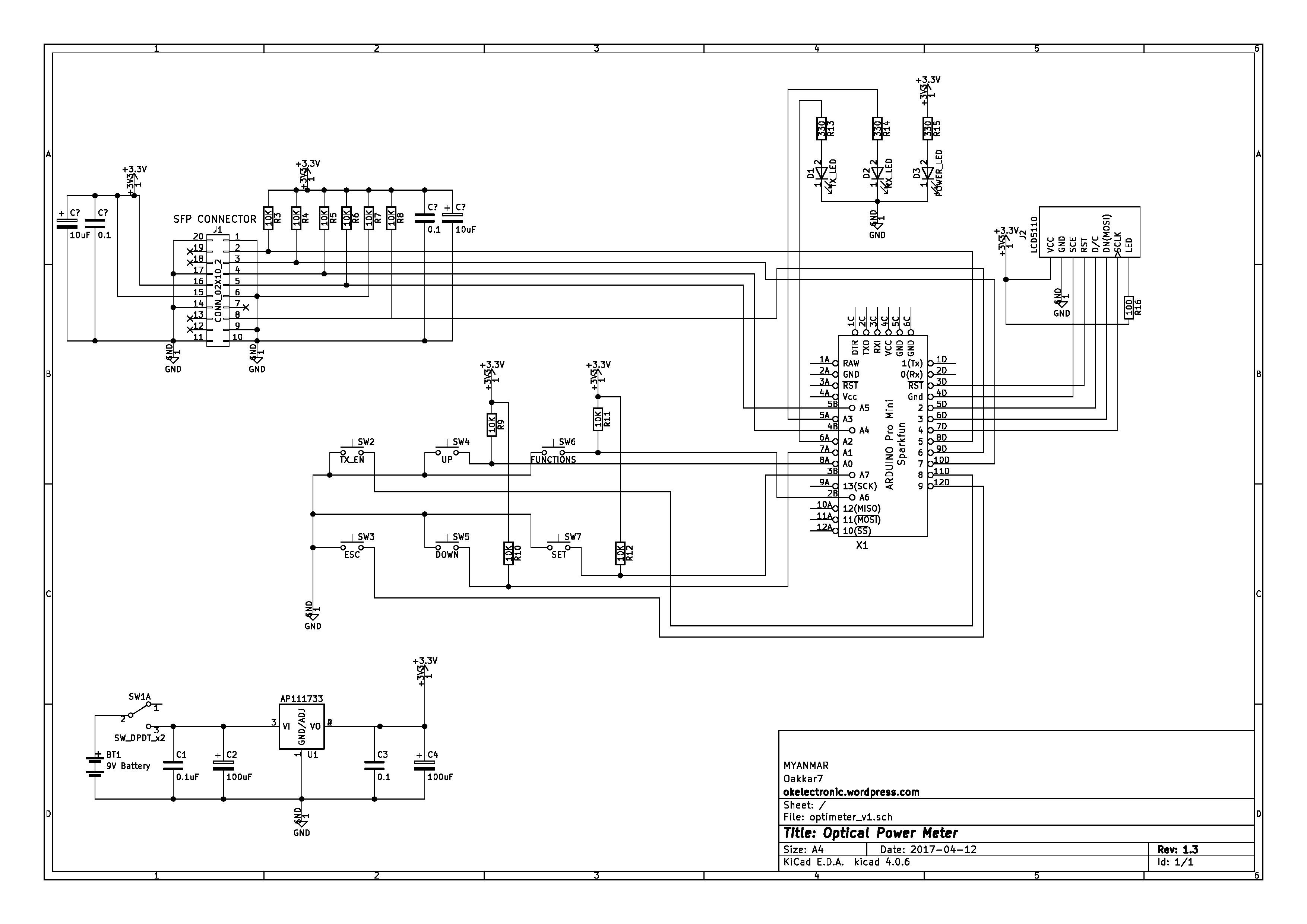
![]()
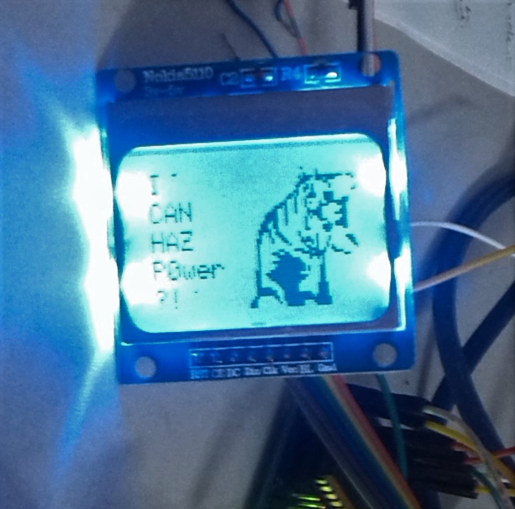
Splash Welcome page, CAN I HAZ POWER
![]()
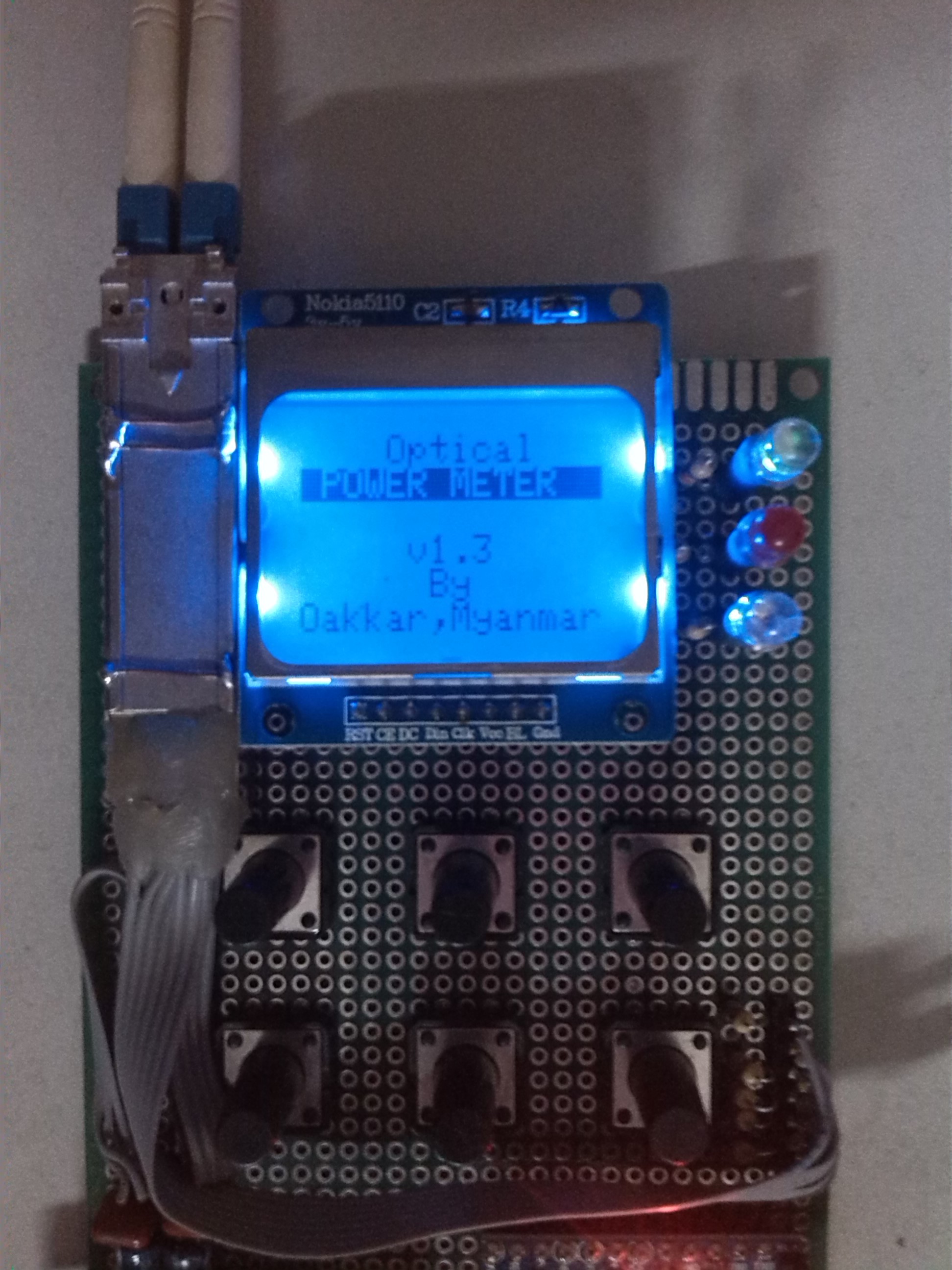
About Page
![]()
Main Menu
![]()
And RX/TX power, TX enable, TX status and Alarm
![]()
-
Phase-3# Arduino DDM Library
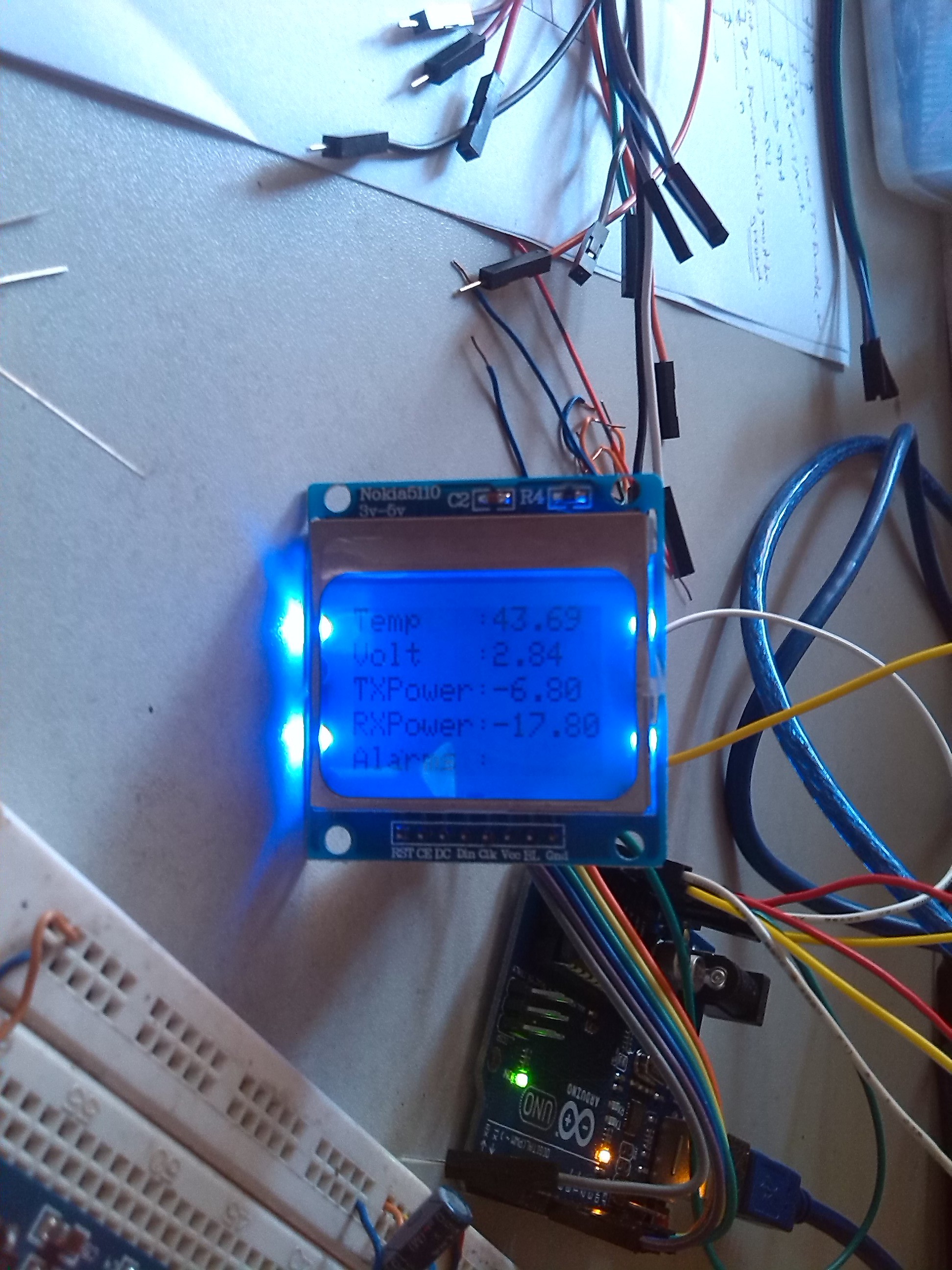
05/01/2017 at 05:26 • 0 commentsNot only building hardware, I like to develop a simple library for SFP/DDM interface. Library supports the following functions.
- Raw Reading DDM Registers (96-117)
- Read TX, RX power in watt and dbm
- Modules Voltage, Current
- control TX enable/disable, mode
- alarm and event monitoring
- Calibration (not work for now, I have to figure out or you may)
- Debug raw, hex and bin string
Library was added to my github repo. It also included a project for working Optical Power Meter.
I am an engineer who wrote the code as my own need and hobby. So, you can used it as your own risk or you may contribute for better results. Any comments, suggestions and correction are welcome.
-
Phase-2# Hello SFP from Arduino
04/30/2017 at 14:21 • 1 commentThe first trial is using existing Lib for DDM interfacing. But there is not much such library and the only one in my eye is SloMusti, Arduino library for interfacing SFP modules and reading DDM.
https://github.com/SloMusti/sfpddm
Unluckily, lib is not work in the first try. SloMusti Github page said that “For communication the specified I2C library is internally initialized, the default Arduino I2C library is not reliable enough and can not be used. Please obtain and install the I2C library by Wayne Truchsess http://dsscircuits.com/articles/arduino-i2c-master-library.html”.
Anwyaw, SloMusti Lib is very informative and structurally formatted and it help me alot how to do things.
So, I try to write my own I2C code snaps with Arduino building lib and it worked. So, I developed by own SFPDDM Lib from scratch. My idea is keep it simple and forward. The first step is to read raw data format from SFP/DDM registers (96-117). These reg are used for monitoring, alarm, control and debugging. Each function of these register and explanations are worth to read from Finisar Application note.
Connection pin outs <--> Arduino UNO are as follow. Be sure to use 5V-3.3V level shifter board.
VeeTs - GND
VeeRs - GND
VccRs - 3.3V
VccTs - 3.3V
MOD-DEF(2) - SDA (4)
MOD-DEF(2) - SDA (5)
MOD-DEF(2) - GND
Then, I tried to read reg(96) with normal I2C Lib (Arduino buildin) and print it out to UART. Then, phrase and formatted.
The first trial output, output from reading DDM register. Look promising.
![]()
![]()
-
phase-1# Preparing SFP for Initerfacing
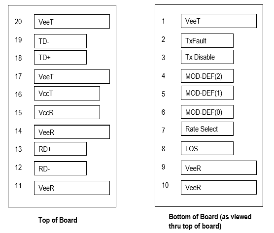
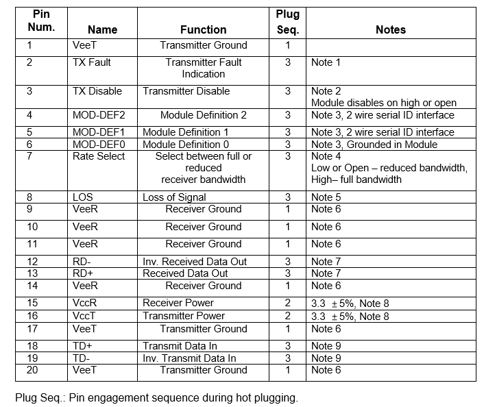
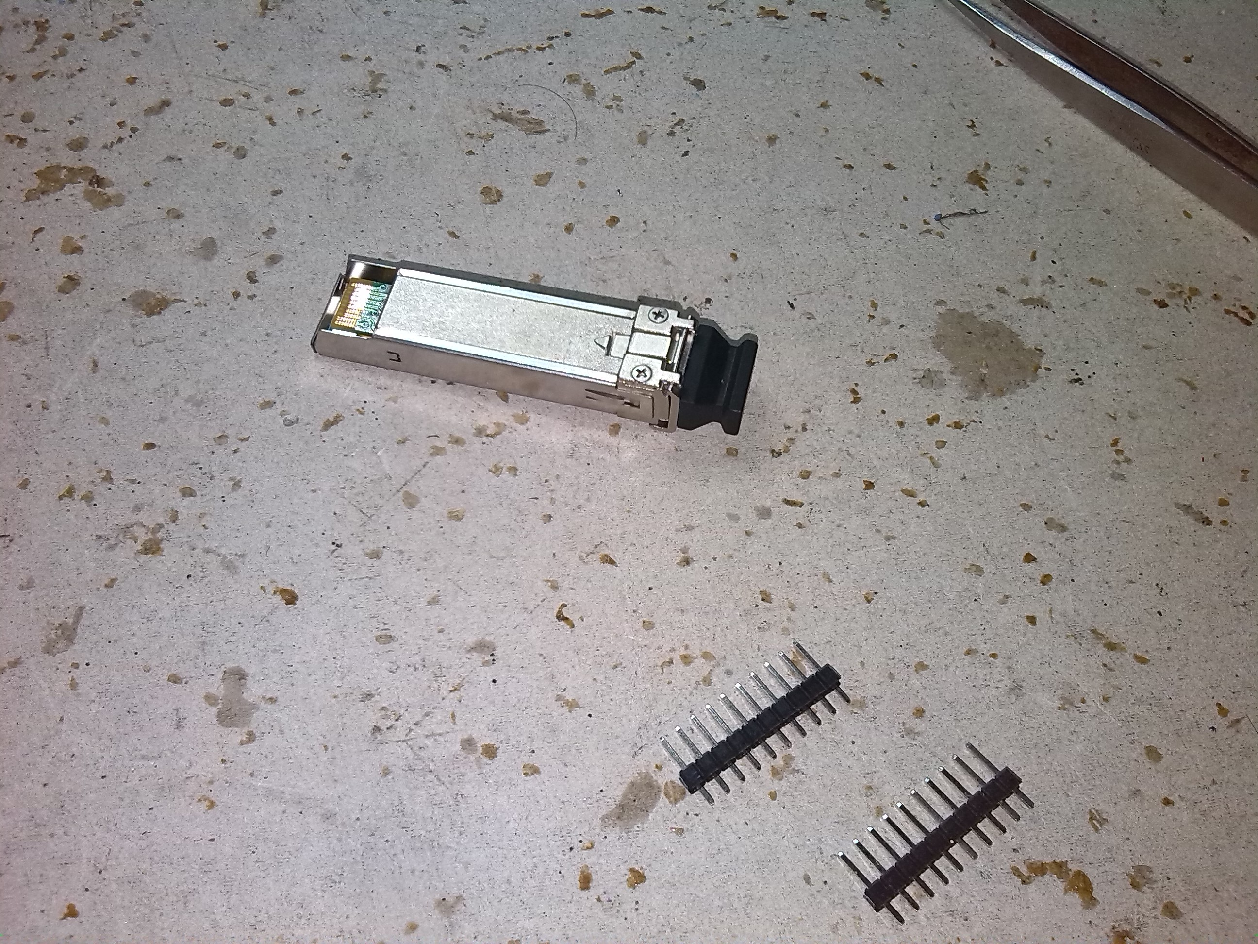
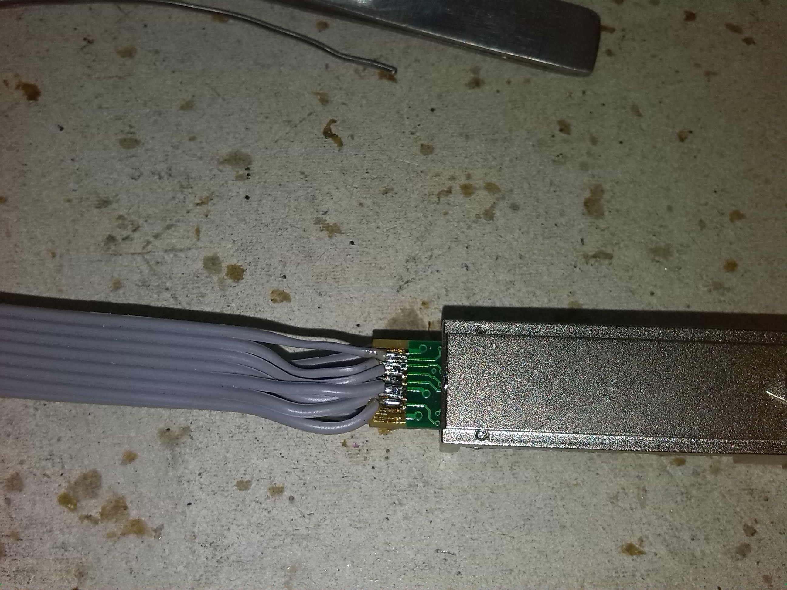
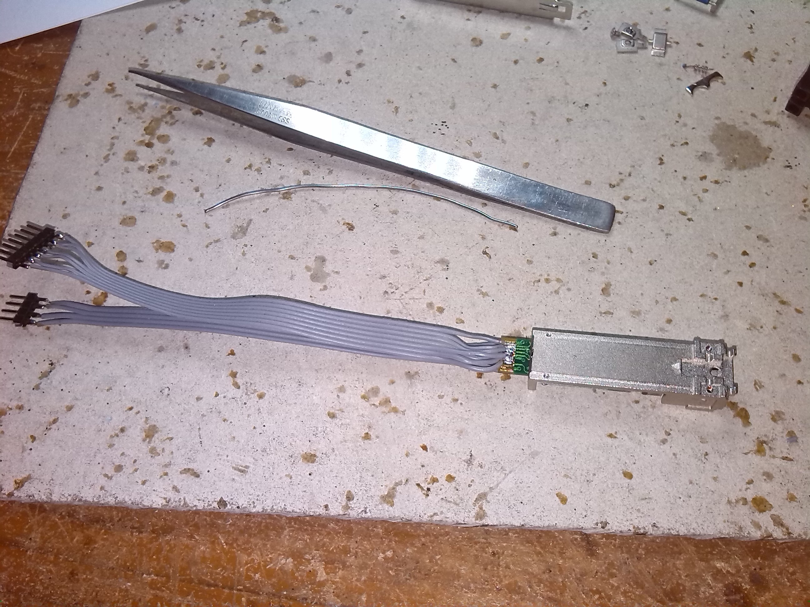
04/30/2017 at 13:40 • 2 commentsThe first and tricky step is to solder SFP modules. The module pin outs is as follows. I need to solder 20 connectors with 20 wires to a standard 1.5mm pin outs. I used Mikrotik S-31DLC20D, a 1.25G SFP transceiver with a 1310nm Dual LC connector, for up to 20 kilometer Single Mode fiber connections, with DDM. But you may use any SFP module without problem.
Another reason I used Dual connector (TX and RX are different fiber interfaces) is to control TX function as additional. Thus, meter can transmit laser source and enable and disable this.
A good ref for SFP modules pin outs from finisar is here:
https://www.finisar.com/optical-transceivers/ftlf1318p3btl
1) Standard SFP pinouts is as follows.
![]()
![]()
2) Soldering and result is as follow. We can omitted Data TX/RX pair pins for now.
![]()
![]()
![]()
Next is interfacing with Arduino
Optical Power Meter (with SFP and DDM protocol)
DIY Optical Power Meter with SFP (Small Form-factor Pluggable transceiver) and DDM (Digital diagnostics monitoring ) protocol
 oakkar7