To allow Morsemode to be used without a direct wired connection, access to an alternate physical medium must be provided. I have chosen to use audible sound through air. This is consistent with the requirement for easy access by unaided human persons, but can also potentially simplify access to electronic communication channels (let MorseMode use the same mic and speaker that a person would; no plugs, no wires! ).
An Arduino Uno or similar microcontroller board can directly generate audio frequency signals on its digital output pins, and is capable of providing sufficient signal energy to directly drive a small audio transducer. The MorseMode prototype currently uses a high impedance piezoelectric 'crystal' earphone as an output transducer.
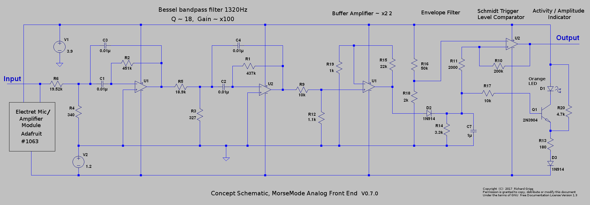
Somewhat more analog circuitry is required to implement the receive function. The initial receiver input stage is an amplified electret microphone module, Adafruit part number 1063. The 1063 module gain control is adjusted to yield an output signal amplitude in the range of 50 to 100mV when exposed to the transmitter audio output of a second MorseMode unit (placed an arbitrarily chosen 30cm transducer separation distance for testing). The signal from the 1063 module is fed to an active filter tuned to 1320 Hz (arbitrarily chosen 3x 'concert a' note). This is a four pole bandpass filter with a Q of 18 and a gain of 100x. The output of the filter is fed through a forward-biased diode to a 1uF capacitor paralleled with 3.3kohms to ground. The time constant of the 1uF and 3.3k ohms is about four times the period of the 1320Hz signal passed by the bandpass filter. The voltage across the capacitor will approximate the shape of the envelope of the output of the bandpass filter. Essentially, this circuit is an AM "crystal radio" operated at audio frequencies.
A Schmidt Trigger circuit is used as a comparator to convert the envelope waveform into a series of high and low digital levels. These levels encode the mark and space states that make up Morse code characters. The MorseMode analog front-end circuit is designed to be powered with rails at 0V and 4.8 to 6.0V. A 'synthetic' analog ground is created at a level of 1.2 to 1.6V. If these voltage levels are used, the output of the Schmidt trigger circuit can be connected directly to the Morse input (Pin 2) of a 5V-powered Arduino Uno.
The output of the envelope detector is also sent to a one-transistor amplifier used as a controlled-current sink in series with an LED. The LED brightness is proportional to the envelope waveform voltage, which can be convenient during system setup and signal aquisition.
A pdf copy of this image is available in the 'files' section of this project
There is an additional signal-processing consideration to address. The bandpass filter has sufficient Q that it "rings" for a significant period of time after the 1320 Hz input signal goes to zero amplitude. This ringing effectively stretches mark states. The length of the ringing interval is primarily dependant on the envelope amplitude at the end of the mark interval. Ring duration is essentially independant of the duration of a mark interval.
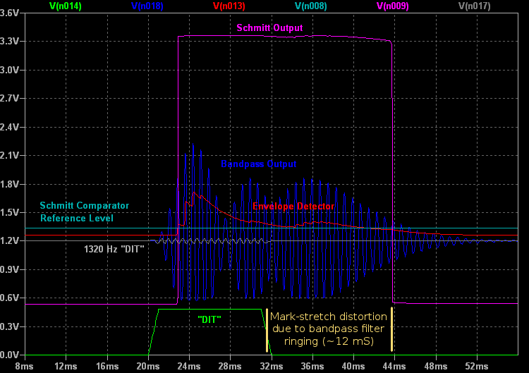
There are several possible approaches to correction of ring-induced mark distortion. The method I have chosen is to make a compensating adjustment in the MorseMode software. A constant time (default 10 milliseconds, can be changed by user) is automatically subtracted from each mark interval, and added to each space interval. This method works fairly well as long as mark interval signal amplitude is reasonably constant. An Automatic Gain Control (AGC) circuit, or even a simple voltage clamp at the envelope capacitor would probably further improve the range of useful input amplitudes.
Discussions
Become a Hackaday.io Member
Create an account to leave a comment. Already have an account? Log In.