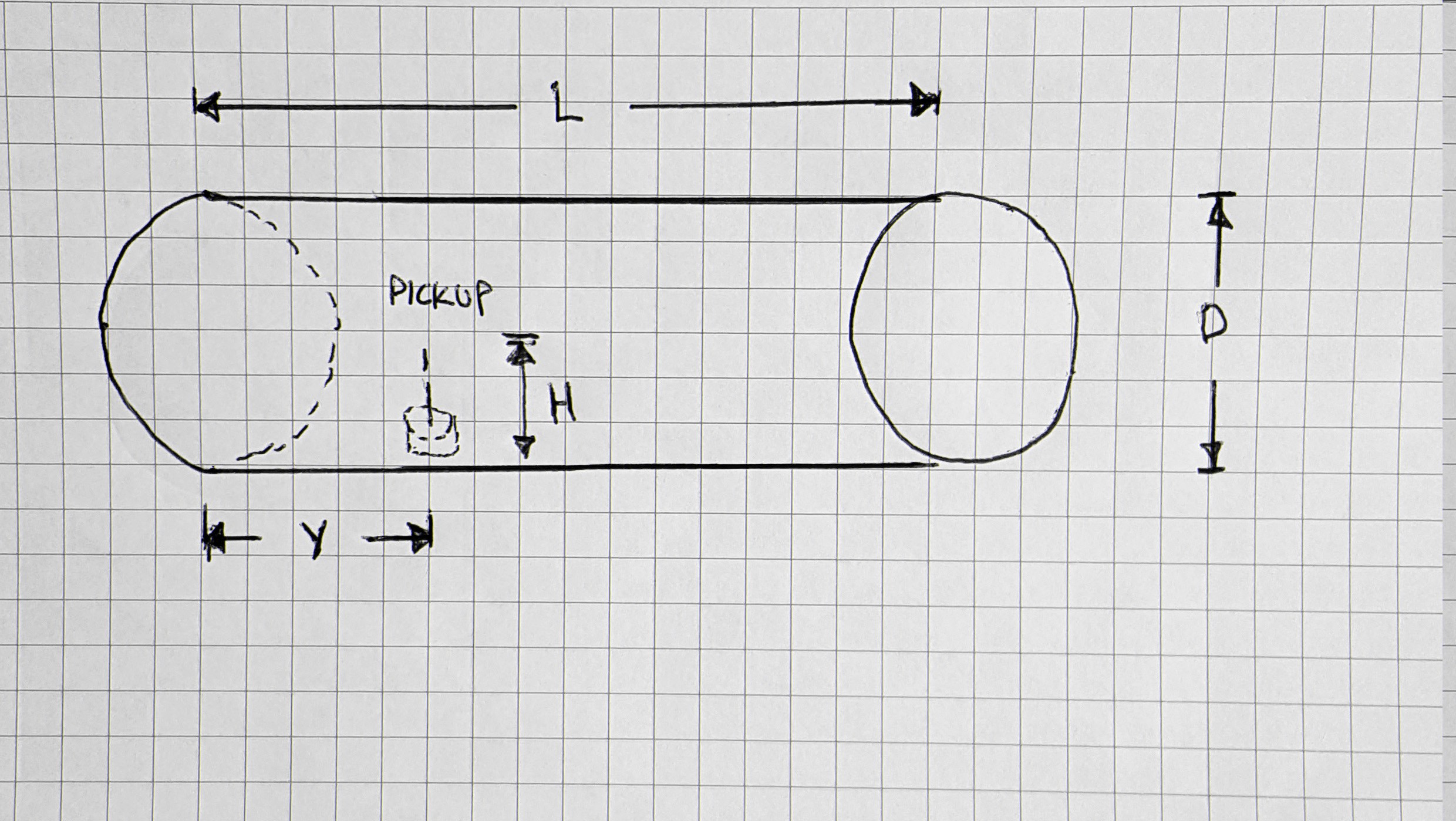
Yagi or parabolic antennaes are the most effective at concentrating the power of the WiFi transmitter in a specific direction but they are complex to design and construct. In order to simplify the construction process and make it easy to construct locally, a cantenna design was chosen. The cantenna is an abbreviation of the word “can” and antenna. In it simplest form it is literally is a can with a pickup mounted a set distance from the closed up of the can.
The most complete information on the optimum parameters to use for a cantenna are covered in the book “Cantenna the Poor Wifi Hackers Choice” by Sven-Erik Zetterström. 1 The important parameters are the diameter of the tube used to form the antenna, distance of the pickup from the end of the tube and the length of the tube
1 Sven-Erik Zetterström. “Cantenna the Poor Wifi Hackers Choice”. https://books.google.ca/books?id=7HNQDQAAQBAJ&pg=PT8&lpg=PT8&dq=large+diameter+cantenna&source=bl&ots=FT2hjm941c&sig=R6-nIGb9FLa6aJeilNkTHRxozvM&hl=en&sa=X&ved=0ahUKEwiI65v09OLWAhVGjFQKHa7fB9AQ6AEIRjAI#v=onepage&q=large%20diameter%20cantenna&f=false .

There are a range of values each dimension can be for the cantenna but the approximate starting values are:
•The length of the can, (L) should be longer than 3/4 of the wavelength
•The diameter of the can (D) should be longer than 1/2 of the wavelength
•The copper pickup element should be approximately 1/4 of the wavelength
•The position of the copper pickup element (y) away from the back of the cantenna (rear standoff) is based off the overall diameter of the can and can be calculated using this on-line calculator:
http://web.archive.org/web/20080316034408/http://www.pelaginox.com/pc/pc-cancalc.html
As mentioned above the copper pick up elements should be approximately ¼ of the wavelength of the carrier frequency. WiFi typically has 14 overlapping channels with most WiFi units are shipped set to channel 6. Some Wi-Fi channel numbers overlap with each other. Channel 1 uses the lowest frequency band and each subsequent channel increases the frequency slightly. Therefore, the further apart two channel numbers are, the less the degree of overlap and likelihood of interference. The three Wi-Fi channels 1, 6 and 11 have no frequency overlap with each other for 2.5 GHz WiFi
“Newer 802.11n and 802.11ac Wi-Fi networks also support 5 GHz wireless connections. These frequencies are much less likely to suffer from wireless interference issues in homes the way 2.4 GHz does. Additionally, the 5 GHz Wi-Fi channel choices available in most home network equipment have been pre-selected to choose only the non-overlapping ones.
Choices vary by country, but in the United States these non-overlapping 5 GHz channels are most recommended: 36, 40, 44, 48, 149, 153, 157 and 161.
Usable non-overlapping 5 GHz channels also exist between 48 and 149, specifically 52, 56, 60, 64, 100, 104, 108, 112, 116, 132, and 136. These channels fall into a specially regulated category where a Wi-Fi transmitter is required to detect whether other devices are already transmitting on the same channel and automatically changes its channel to avoid conflict.”1
1 https://www.lifewire.com/wifi-channel-number-change-to-avoid-interference-818208
As a run of thumb for 2.54 GHz WiFi cantennae:
“Driven element length never, ever, changes, and is always 31 mm. You will see many instances of online advice that say different; they're wrong. To optimise it for Channel 1, you can make it 0.5 mm longer; to optimise for Channel 11, then 0.5 mm shorter. Otherwise, leave well alone. For practical purposes, it is always left at centre band optimum length, which is around 31mm.” 1
The current design follow this rule of thumb without issues. Implementations should vary the pickup length depending on the needs for their particular system though. In most rural installation it should not be necessary to experiment too much with pick up height as there should be few devices that should interfere with the system.
Though not the optimum diameter 4 inch heater duct is quite common and comes in 5 foot lengths so that cantenna can be made of a customized length easily with tin snips. Based on a 4 inch diameter for the cantenna the following dimensions apply:
1 http://web.archive.org/web/20080316034408/http://www.pelaginox.com/pc/pc-cancalc.html
|
Dimension |
Length |
|
Diameter |
4 inches |
|
Length |
5.165 inches |
|
Position of pick from back of cantenna |
1.712 inches |
|
Height of the pick up |
1.22 inches |
Though you can get away with a cantenna that is as short as ¾ wave it is suggest that you use at length that is equivalent to two times the ¾ wave length.
The calculations above are for a 2.4 GHz WiFi antenna. The 802.11 workgroup which defines WiFi has documented use in five distinct frequency ranges: 2.4 GHz, 3.6 GHz, 4.9 GHz, 5 GHz, and 5.9 GHz bands. 1 2.4 GHz and 5.0 GHz are the most common consumer bands. The other bands are reserved for special uses such as vehicle and emergency applications . Each range is divided into a multitude of channels. Countries apply their own regulations to the allowable channels, allowed users and maximum power levels within these frequency ranges. The calculations for the cantenna will therefore vary depending on the frequency band used.
1 IEEE 802.11-2007: Wireless LAN Medium Access Control (MAC) and Physical Layer (PHY) specifications". IEEE. 8 March 2007.
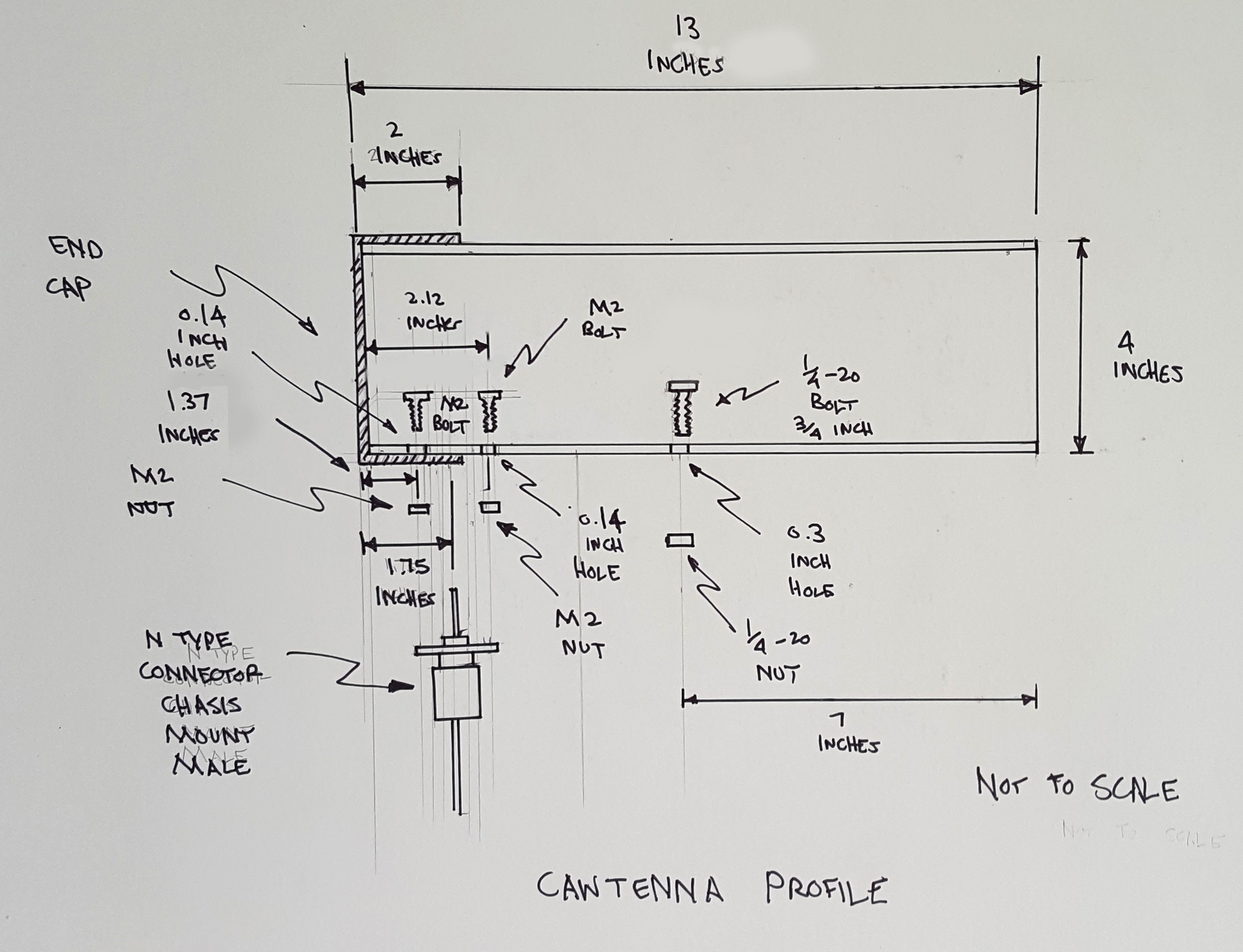
The diagram below shows the assembly diagram for the cantenna.

It is made up of:
|
Item Number # |
Part |
Number of Parts |
|
1 |
13 inch section of 4 inch heater duct |
1 |
|
2 |
4 inch heater duct end cap |
1 |
|
3 |
Chasis mount Male N-type connector |
1 |
|
4 |
M2 bolts |
4 |
|
5 |
M2 nuts |
4 |
|
6 |
¼”-20 bolt 1 ¼ long |
1 |
|
7 |
¼”-20 nut |
1 |
|
8 |
2 flat washers |
2 |
|
9 |
Male N-type connect to SMA cable |
1 |
The ¼-20 thread bolt chosen as it fits into a threaded mount that can be attached to a camera tripod for test.
Each node can use a single cantenna or it can split the signal between 4 cantennae positioned perpendicular to each other to reach the other nodes around it if the nodes are laid out like a grid. A signal splitter can be used but the power is equally distributed among the 4 antennae reducing the effective distance of each antenna.
Discussions
Become a Hackaday.io Member
Create an account to leave a comment. Already have an account? Log In.
No calculator works for me for some reason, I want to make a cantenna and all my measurements are correct except the position of the pick from back of cantenna... diameter is 65mm and lenght is 96mm, please help me... PLEASE!
Are you sure? yes | no