Close
0%
0%

'fresca' versatile temperature controller

Control temperature for up to 8 separate processes! Cooling/heating control with humidity sensing. Based on Arduino and DS18B20/DHT22.

leoLeo
Similar projects worth following
Control temperature for up to 8 separate processes! Cooling/heating control with humidity sensing. Based on Arduino and DS18B20/DHT22.

The current code is WORKING in github and has the following features:

* +-0.5deg celsius accuracy from -10deg to +85deg without calibration (Higher accuracy is possible through calibration) (DS18B20)
* Relative humidity sensing with DHT22 sensor
* Interactive menu to modify sensor/temperature control parameters
* Monitoring of temperature for each sensor on 7-segment displays, regardless of user input
* CoolOn/CoolOff and HeatOn/HeatOff thresholds offer hysteresis-like temperature control for each sensor
* Offset calibration for each sensor, stored in the DS18B20's EEPROM (each sensor will store the calibration data)
* Storage of settings in Arduino's EEPROM
* Sensor CRC and presence checking (no wrong read-outs)
* Temperature display in celsius/fahrenheit

Would love feedback and feature requests. Enjoy!!! :)

*** WORKING CODE is in github repository!!! *** https://github.com/lcapossio/fresca

Check the README.md for more info


Usage of fresca

Main menu


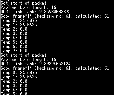
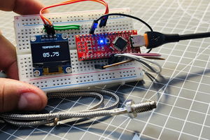
All user input/interaction is displayed on the LCD, and user input is possible by using the keypad. The 7-segment displays monitor the temperature of each sensor. This is regardless of what mode the program is in. Temperature updates every second (actually a bit faster, around 900ms)

Menu navigation

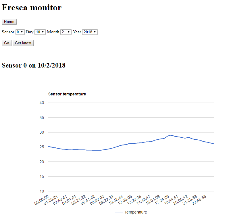
On the main screen temperature is displayed for the current selected sensor (default sensor 0). Using the UP/DOWN arrows selects a different sensor. Pressing LEFT/RIGHT buttons will toggle temperature/humidity display (for sensors that support it)

While on the main screen, if the SEL key is pressed the program will enter configuration mode for the given sensor. The first configuration screen the 'CoolOn' threshold can be modified. Use LEFT/RIGHT arrows to change the temperature above which the relay for cooling will be activated. Then press SEL. The next screen modifies the 'CoolOff' threshold, also set it with LEFT/RIGHT arrows. If the temperature falls below this threshold the MCU will deactivate the respective relay. The next screen is accessed by pressing SEL again.

The next two screens are dedicated to the heating part of the controller. 'HeatOn' will turn on the heating relay if temperature falls below this threshold. When you are done press SEL to continue. 'HeatOff' will turn off the heating relay when temperature rises above said threshold. Press SEL after this to continue to the offset calibration.

This screen allows to modify the offset of the temperature reading of the sensor. This gives the possibility to calibrate the sensor to a known reference temperature. By pressing SEL once more, all settings are saved and the program returns to the main screen.

NOTE: If heating and cooling parts of the controller overlap, cooling will take precedence.

NOTES

Source code is released under GPLv3, please read LICENSE for more information

*PD: The project is called 'fresca' in reference to Argentinian slang word used to describe a cold beer! :)*

  • 1 × Arduino Mega 2560
  • 8 × DS18B20 Sensors / Temperature, Thermal
  • 1 × LCD keypad shield Main display device and key inputs
  • 8 × 7 segment displays Temeprature monitoring displays
  • 8 × 5v Relays Temperature control switching

View all 6 components

  • 'Holding' your ground

    Leo11/05/2018 at 05:42 0 comments

    Hi all!

    For those of you who are setting up projects with inductors, coils, motors, relays and other big inductive things alongside electronics, I have a piece of advice. Most of the time we have to be mindful of them. While setting up 'fresca' to run in a real beer brewing environment, I ran into a lot of trouble with inductive back-spikes. It is a very well known and documented subject for engineers working in industrial environments, but for some people it's not clear as to what happens and when it can become a problem.

    Going through school, we used to use a lot of relays, and what your teacher tells you from the first day is: 'you better put an 'anti-parallel diode' across the coil of the relay', and rightly so, you wouldn't want to burn your transistors by the dozens. What is happening? It turns out that inductive elements, like the coil of a relay, store energy in the form of magnetic flux in the coil's core. When you turn-off the current flowing through it, it will try to continue how it was (with the current flowing) until it runs out of energy. Since the circuit is open, it's almost impossible to keep a substantial current running so the physics kicks-in (think Faraday's law) and there's a huge reverse voltage spike applied by the inductor in order to keep the same current flowing. This voltage back-spike could be in the order of kilo-volts (many times it is). So if you have a transistor turning on/off a coil it will face the inductive back-spike each time it turns it off, and that would exceed the maximum permitted collector-emitter voltage (or drain-source for FETs) in turn destroying the transistor.

    Now the diode in anti-parallel configuration is there to fix that problem. Since it's in anti-parallel, the diode won't conduct current most of the time (remember, its resistance to reverse voltages is ideally extremely high), but it will conduct current when the transistor turns-off and the relay's coil creates the reverse voltage back-spike (this reverse voltage is forward-biasing from the diodes perspective). This saves our little transistor from having to withstand that massive voltage transient since the diode will conduct all the excess current until the coil runs out of energy. Wonderful and elegant, huh ?

    Now if we have AC current, we can't use a single diode to mitigate this effect, since current is flowing in both ways and we don't know exactly the direction of the current when it gets turned off. The solution is in using two Zener diodes in series (and in turn parallel to the coil, with both cathodes facing opposite directions), which will not conduct during normal operation, and will start conducting once the back-spike rises close to the Zener voltage. That means we have to choose the Zener voltage of the diodes to be higher than the peak value of our AC voltage so no conduction happens during normal operation of the circuit.

    Now, luckily, there are diodes created only for the purpose of suppressing these voltage back-spikes, they are called Transient Voltage Suppression diodes (TVS diodes). They come in two flavors, unidirectional (DC applications) and bidirectional (AC applications). One important parameter of these diodes is 'Maximum reverse stand-off voltage', this is the maximum voltage at which no current is conducted by the diode hence it has to be selected according to the DC or AC voltage of the application.

    There is another solution, but it requires a bit more thought to work properly. It works by using a resistor and a capacitor in series, which are in turn parallel to the coil. This circuit is called a 'snubber' circuit. The values of R and C have to be calculated and that usually means we need to know/measure the resistance and inductance of the coil. You can find more information about this method on the internet.

    So how did this affect me in my project you're wondering. All the relays I used were opto-coupled and protected by diodes so they wouldn't destroy...

    Read more »

  • fresca-link and webapp looking sharp!

    Leo02/14/2018 at 09:06 0 comments

    Hi all, happy new year for all, it's been a long time since last update, but I haven't stopped working on the project.

    I finally got around to create a python webapp using flask. flask is a micro-framework for developing web apps with python. The webapp is currently able to display in a chart all log data from fresca-link temperature updates. The charts are being generated using Google Charts.

    If you can't imagine how all this looks like, take a look at the following pic:

    ... it's the barebones, but the functionality is there. You just need to point at the directory where the log files reside and the webapp will take care of everything (uncompressing, parsing and formatting). Then select the desired day of the year that you wish to view, the desired sensor, and it will be neatly displayed in an interactive nice chart.

    The log files are created by connecting the arduino and the Raspberry Pi using fresca-link (it will generate one log file per day), then fresca-link will get the data from the sensors and output a nice CSV format log file, and, when it is done for the day, it will compress the file to .tar.gz format to save space (log files can get to 10s of MB depending on the sampling interval).

    I will be cleaning up all the code, committing it nicely with documentation to github in the next weeks, and then next move on to more features! :)

    Stay tuned!

    Leo

  • NEW feature, send temperature updates to Raspberry Pi through 'fresca-link'!

    Leo12/20/2017 at 00:03 0 comments

    Hello all!

    I've been working on a new feature that will enable communication with a Raspberry Pi or another device that has a UART port. I've called it fresca-link. The idea is to send binary packets of data via UART to update the 'host' with real-time data from the Arduino. fresca-link is a packet based protocol designed for 8 bit microcontrollers that have low processing power. So, most of the protocol-specific words are 8-bits. I've used simple integer checksum for error protection (CRC is either too slow or takes up too much memory). Data sent over the serial link is binary not ASCII! So you can't possibly debug it by sending the output to a console.

    Since the arduino is pretty busy with real-time tasks, the master of the communication will be the arduino (hence it will only start communication when it know there is no real-time event coming in the next 100ms, for example). The arduino will send packets first to the host, and then the host will respond accordingly (if necessary). Right now I've tested sending temperature update packets to the raspberry pi, and that works like a charm. Later I plan to make it possible for the 'host' to send configuration data to the arduino so that everything can be remotely controlled.

    This is all working on branch 'feat/fresca_link'. Remember to use a level converter 5v <--> 3.3v if you are using a raspberry pi or any other 3.3v part. The raspberry pi receives temperature data by executing a Python script that searches for this 'temperature' packets and displays the parsed temperature on the screen (raspberry pi serial port should be enabled and the serial console feature should be disabled, remember to match baudrates as well). All the arduino code is in the 'arduino' folder, and all the raspberry pi code is in the 'rpi' folder.

    Next step would be to create a webserver in the raspberry pi (possibly using 'flask' or 'django' frameworks) to display all this information and have a control panel for configuring fresca's settings. Stay tuned!

    PD1: You might see a branch called 'feat/SPIcomms' which will die there, where I tried using SPI as a low-level protocol for fresca-link. Since it's rather inconvenient to use the raspberry pi as an SPI slave, I had to use it as SPI master, and that proved to be very unreliable since the arduino can't respond when it's busy doing real-time tasks (like reading the sensors). It also only reached 100Khz max, so that's about the same speed as UART 115200 (the arduino should do better, but maybe I had a problem with the cables or the level converter, anyway I can't see cause I don't own a scope). Overall it turned out to be very inconvenient, so I turned to the simple and reliable serial port.

    PD2: If anyone is interested I can describe the particulars of the fresca-link protocol

  • DHT22 official support, automated builds and more!

    Leo12/13/2017 at 00:14 0 comments

    Hey, I've merged the feat/DHT22 branch back to master, officially supporting the DHT22 sensor. Note that the design can deal with any combination of DS18B20/DHT22 sensors. Relative humidity for DHT22 is only used for display in the LCD for now (press left/right keys in the sensor screen), with further improvements planned ahead.

    Also note that the project has been restructured to work with automated build tools (files have been moved to different folders, and new libraries were created). It supports 'Arduino-Makefile' and 'platformio' (look for instructions in README.md). The repo now contains submodules, so make sure that when you pull you use:

    git pull --recurse-submodules

    and if you clone a fresh copy use: 

    git clone --recursive https://github.com/lcapossio/fresca.git

     That's all for now, in the future I plan to add a webserver feature, most likely with a Raspberry Pi Zero W connected via SPI (there is a webserver branch that uses an ESP8266, but that turned out to be very unreliable and slow)

    Stay tuned!

  • Support for the DHT22 and humidity sensing!

    Leo11/24/2017 at 09:18 0 comments

    I've started a new branch with initial support for the DHT22! The branch is called feat/dht22. Currently it supports configuring DS1820/DHT22 on a per sensor basis, so you can have any combination of them! You can also display the current humidity on the LCD screen instead of the temperature.

    More updates coming soon.

  • Major update, new feature!

    Leo05/30/2017 at 09:58 0 comments

    Hey! Just wanted to let you guys know that I keep working on making this project better. This time there is a new feature as well as new C++ classes. The code has been working for a while and I've just been trying to improve the overall readability and modularity.

    The new feature are the Heating Controllers. Now, apart from having an actuator that controls CoolOn/CoolOff thresholds, there is n actuator that changes temperature by making it rise (whatever heating element you connect to your outputs). This means you now have two more thresholds per sensor, HeatOn and HeatOff. Intuitively it's the reverse operation of the Cooling actuator, when temperature falls below the HeatOn threshold, the actuator will activate and will continue active until it rises above the HeatOff threshold. Keep in mind that if the 'Cool' and 'Heat' thresholds overlap the 'Cools' will take precedence (isn't that logical ? :) )

    Now you can also enable/disable Cooling or Heating actuators on a per sensor basis (in fresca.ino look for 'g_CoolerEn' and 'g_HeaterEn'). The menu now contains the respective screens to change the new thresholds interactively through the keypad.

    The new classes I added aim at offloading some code into separate files and making things more transparent from 'fresca.c' This classes are 'TempActuator' and 'TempController'. 'TempController' instantiates and manages up to two TempActuator classes (one cooling and one heating). The 'TempActuator' class controls the switching of the output actuator as well as the limits for having sensitive thresholds. They both reside in the files 'TempController.c' and ''TempController.h'


    That's all for the moment, just also wanted to let you know that in the near future I'm going to add support for a Wifi webserver using an ESP8266 shield, it's exciting!

    Cheers,

    Leo.

  • New DS1820 class!

    Leo05/13/2017 at 09:13 0 comments

    Hey, I have a new update, I'm adding a DS1820 class to make things cleaner and more portable, this class is based off of OneWire class and it contains methods for starting temperature conversion, reading scratchpad and writing user bytes. It looks good! Functionality hasn't been changed, if you want this new class checkout the 'feat/ds1820_lib' branch.

    I'll have more updates in the coming weeks, I will add a Wifi shield to make a wireless webserver to monitor temperature remotely.

    Stay tuned!

    Leo

  • First update!

    Leo05/01/2017 at 10:35 0 comments

    The main code of 'fresca' is working! I tested it thoroughly and it seems to work beautifully. Temperature monitoring and controlling, as well as the user interface are ready to use.

    Hope the project is useful to someone else, more improvements are coming. I would love feedback/critiques, as well as feature requests. Also if you use it successfully please comment. If you have any question don't hesitate to ask!

    Cheers,

    Leo

View all 8 project logs

  • 1
    Build instructions

    The project build is now automated by using either **Arduino-Makefile** or **platformio** (your choice), you can still use **Arduino IDE** as well.

    The default build is for Arduino Mega2560, but this can be ported to other boards.  

    **'PLEASE NOTE:'** This repo contains submodules, so for the first time cloning the repo you can do it like this: **'git clone --recursive https://github.com/lcapossio/fresca.git'**, or if you already cloned 
    you have to initialize the submodules: **'git submodule update --init --recursive'**. Also each time you pull, you have to pull recursively, in case there is an update for the submodules: **'git pull --recurse-submodules'**  

    Using **Arduino IDE**:  

    * Add all the libraries under **'arduino/lib'**
    * The main sketch is **'arduino/src/fresca.ino'**
    * Compile and upload the sketch

    Using **Arduino-Makefile**:  

    * **'cd'** to the **'arduino/src'** folder  
    * run **'make ARDUINO_DIR=your/arduino/install/path'**  

    Using **platformio**:  

    * **'cd'** to the **'arduino'** folder  
    * run **'platformio run'**  

    ### Configuration/Pinout
    The configuration/pinout for the code can be modified easily in **'arduino/lib/fresca/fresca_pinout.h'**. Look at the commented description of each line to know what they are used for.

    Keypad is connected to an analog pin.
    Each sensor is connected to a single digital I/O.
    7-Segment displays CLK pins are connected to a single arduino digital pin.

View all instructions

Enjoy this project?

Share

Discussions

halvespatwer wrote 07/10/2023 at 14:58 point

There has been a great deal of value to me in my involvement with the project. Would like to share it with the where to put temp probe in brisket team so they can also read it and implement something new.

  Are you sure? yes | no

Leo wrote 12/12/2017 at 08:28 point

Hi Thomas!
Thanks for the compliments, I've worked quite a bit on it despite being a simple project I'd like to add more features little by little.

Yes I think it should have better visibility as well, how do we create a new list in HaD ?

  Are you sure? yes | no

Thomas wrote 12/12/2017 at 20:00 point

Hi Leo, thanks for the follows :-)

I don't know how to ask for a list yet, but I put the question on the .stack:
https://hackaday.io/page/4067-proposed-list-for-process-or-enviromental-controllers

  Are you sure? yes | no

Thomas wrote 12/10/2017 at 22:15 point

Nice project, with docs on GitHub, and all. I like it!

It's a pity that it hasn't a better visibility. Maybe we should ask for a "process control" or "temperature control" list in HaD?

  Are you sure? yes | no

Similar Projects

Does this project spark your interest?

Become a member to follow this project and never miss any updates