 Morning.Star
Building the Kooga
I'm still waiting for the ESP8266 I ordered, so while I was hanging on that I put a POC prototype together.
Using an Arduino to drive 805 LEDs is the closest I can get to a NeoPixel strip as well, so I've used 8 LEDs for the Landing Strip and a further 3 for the badge. One more to drive the Host Signalling and thats an Arduino maxed out.
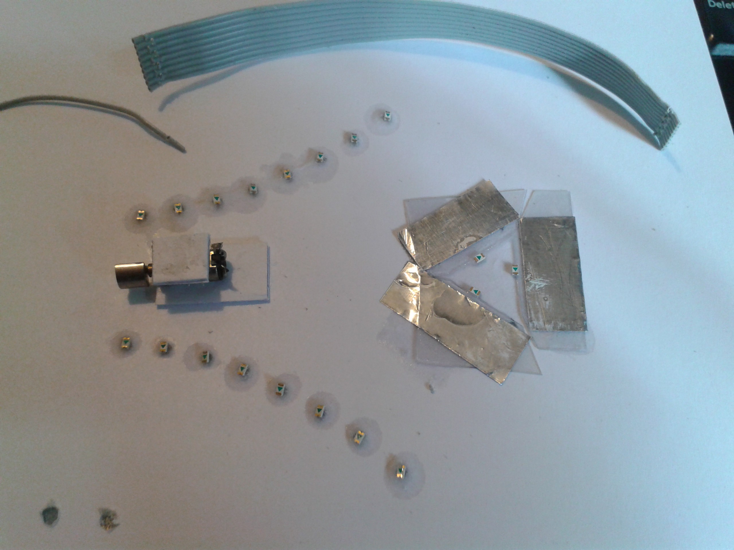
The badge is constructed using waveguides. The front surface of a thin piece of transparent plastic is roughened, and a LED set into the edge. A piece of reflective foil behind it makes sure a lot of the light crossing the plastic horizontally gets scattered and trapped by the rough surface where it is visible.
I've used superglue to interface the LED directly with the waveguide itself to maximise the light transfer.
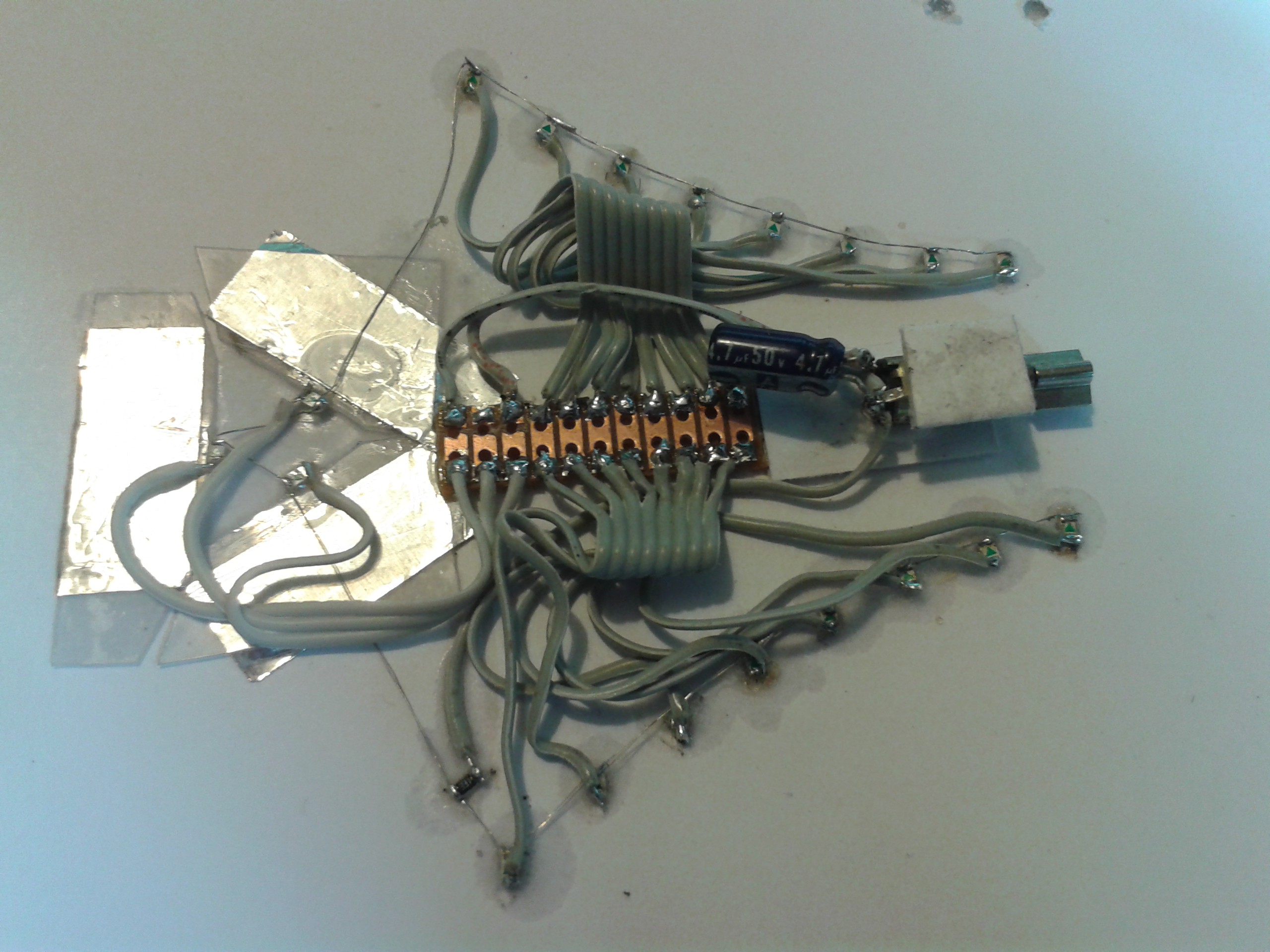
Wiring in all the grounds, adding series resistance and a buffer/flyback for the motor. Normally a suppressor would be much smaller and a ceramic type. Here I'll be driving the motor with PWM so a larger buffer is best.
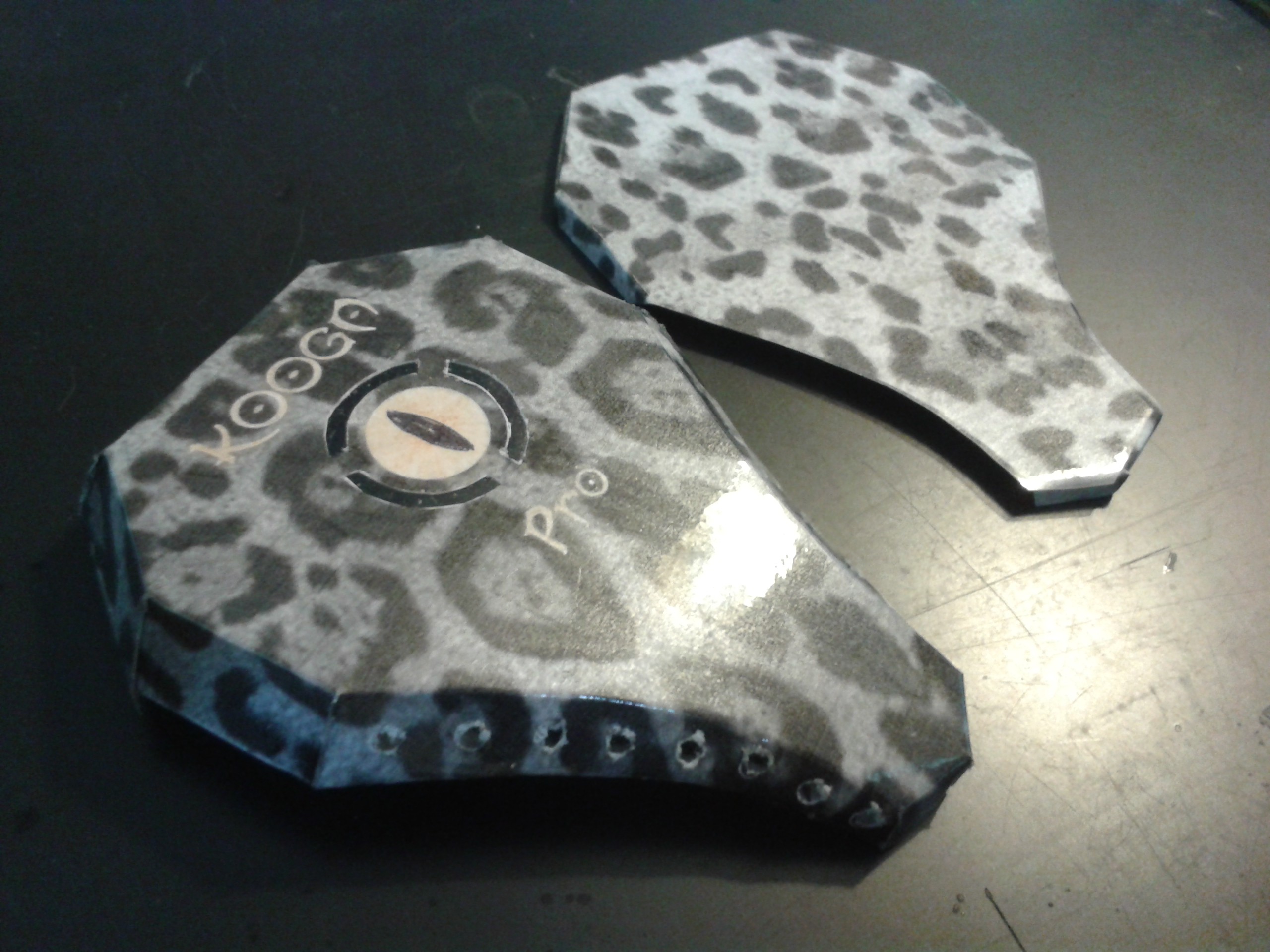
The case is double-printed with the folding template on one side and the Kooga design on the other and coated with sticky-back plastic before folding so it stretches evenly over the curved surface.
I managed to get quite a shine on that.
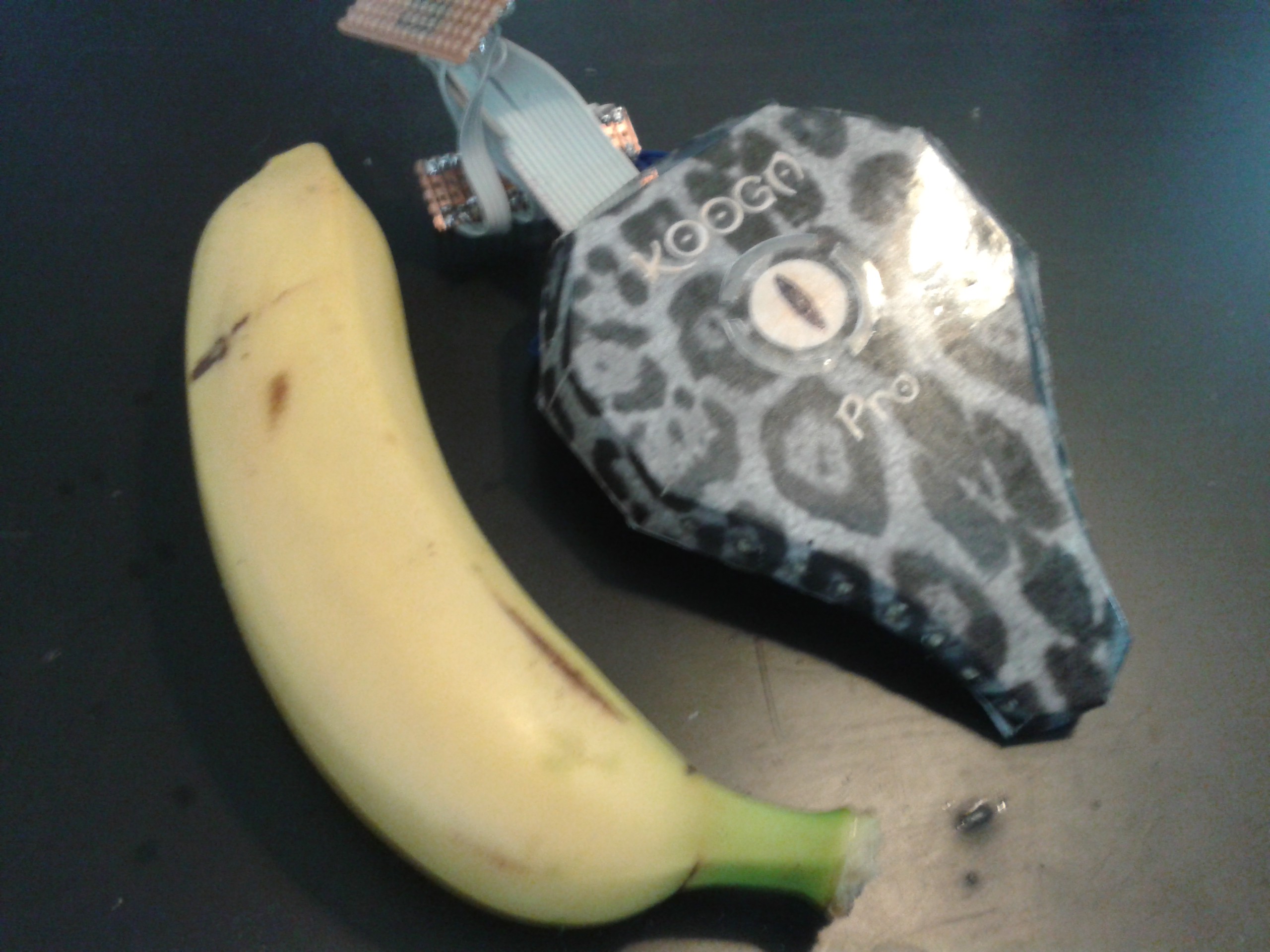
The obligatory banana for scale. Note that this is a fun-size banana for testing. I've never used a banana before so I started with a small one.
I need to swap out one of the badge LEDs which doesnt work and one of the Landing Strip seems to have packed up too, it worked during testing.
I also had a bit of trouble matching the LED drive current. I ordered bright white 805s and got green, so I just shrugged and used them. Unfortunately the white ones are 3V 30mA, and the green ones are 1.8V 20mA so I wound up building a divider after blowing the first print up. Oops...
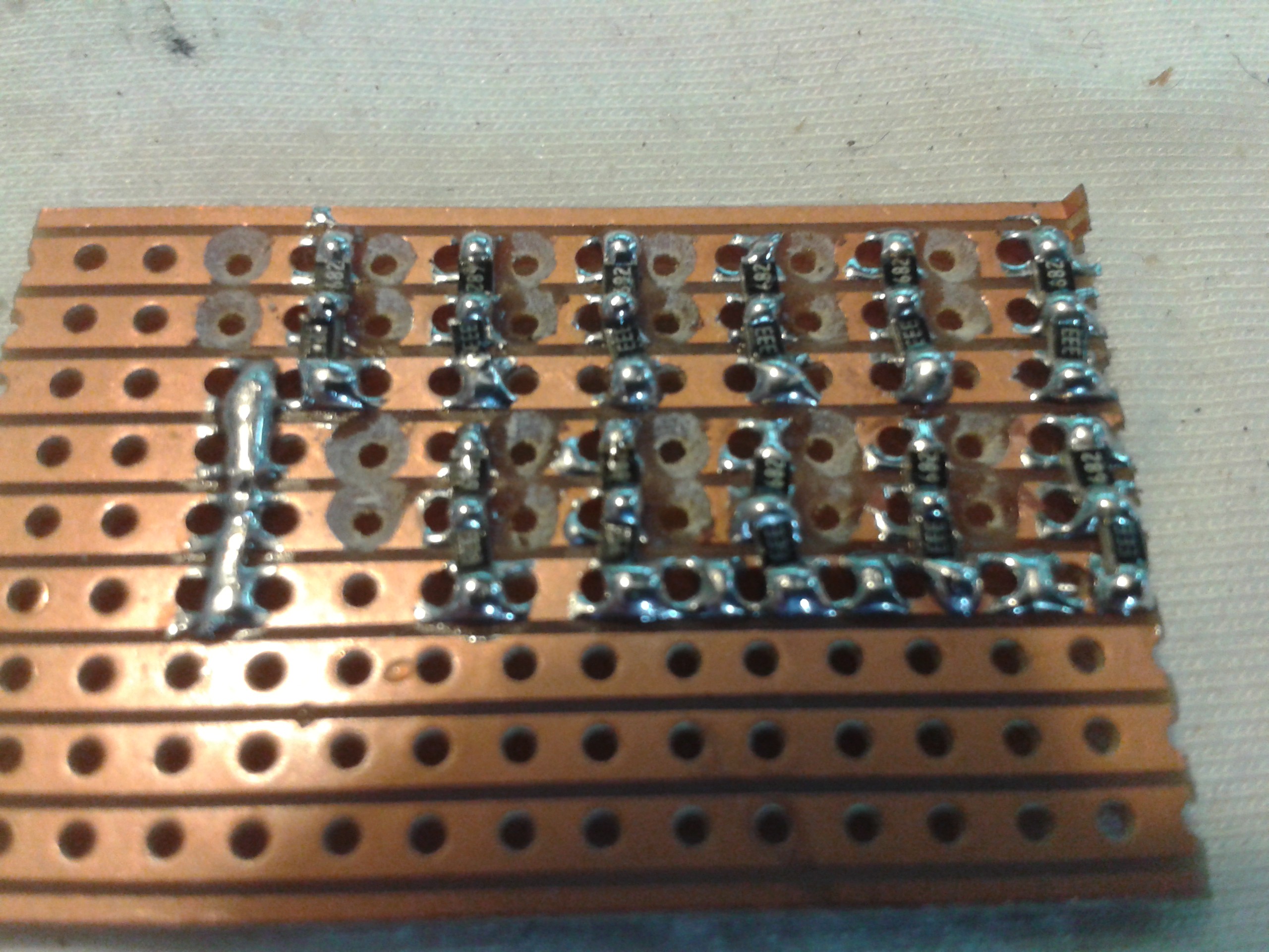
I originally had a 330ohm series resistor in it (Vs=5V - Vf=1.8V / i=20mA : R = 160) which should have been fine but it blew using 3V to test them. So I built a divider using 6.8K and 3.3K resistors and shunted the power I needed instead. I'll work on this...
There is also a capacitive touch sensor behind the badge to turn it on and personalise the vibes, it isnt enabled yet...
Discussions
Become a Hackaday.io Member
Create an account to leave a comment. Already have an account? Log In.