 Tron9000
Finding a switch
As usual I first looking in my spare parts box for bits, I found 2 candidates for my switch that would select the interval for the timer:
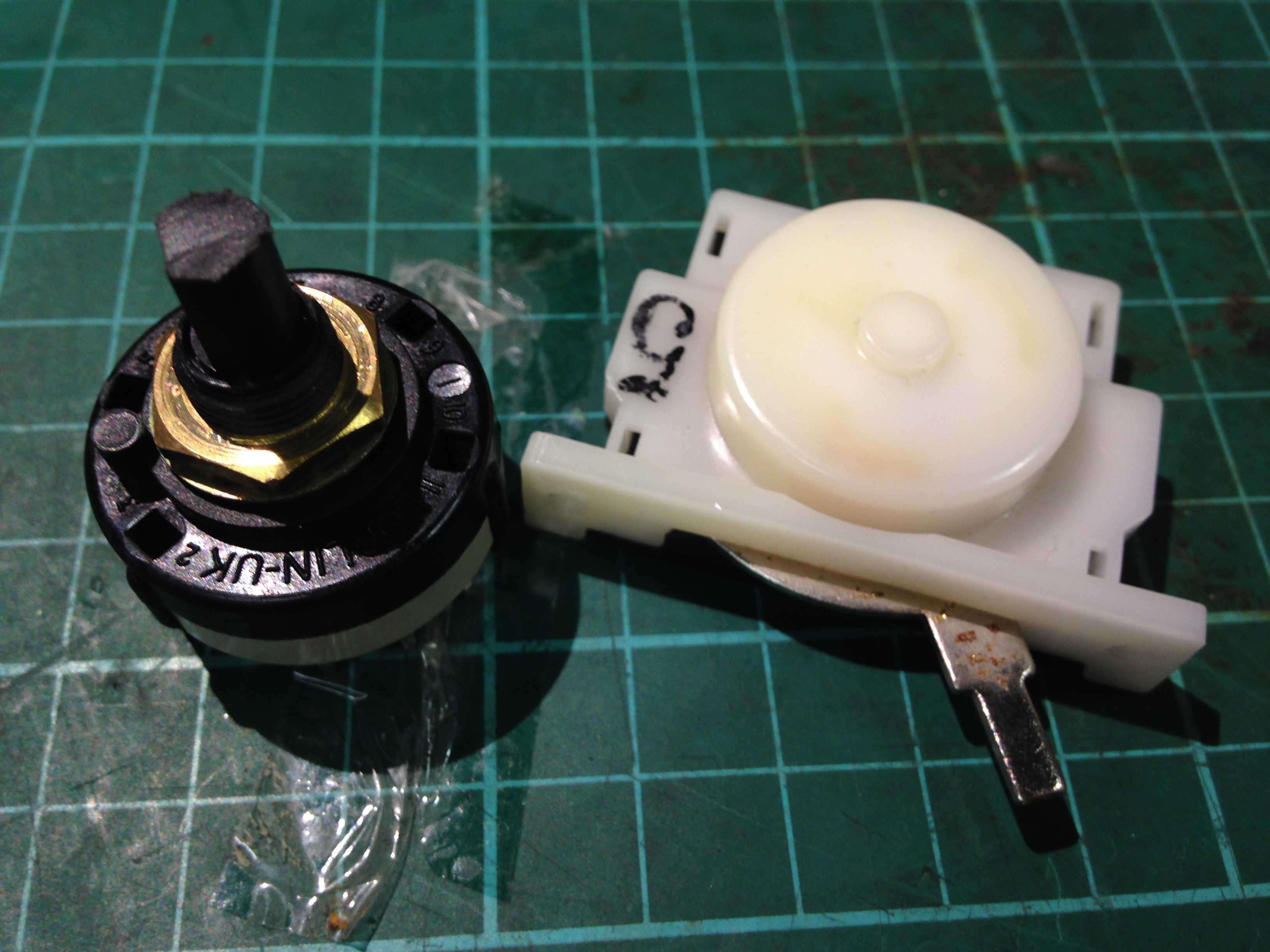
Action is important in this case, it has to be a very positive 'click' and hold its position firmly as not to change whilst driving along. The white one on the right had a slide action and all the attributes I needed, but unfortunately had strange contact configuration! the Black rotary switch on the left had the same attributes, was single pole and could have up to 12 contacts, which could be configured by moving a ring with a tab in it under the nut. So a clear winner.
Building the prototype
Firstly I determined what intervals I wanted: 10 seconds, 15 seconds and 30 seconds. This allowed me to work out my required resistor values for R1 from the 555 astable equations.
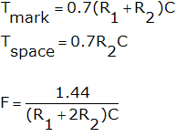
I choose C1 = 100uF and R2 = 15k (10K+4k7) so the time the LED is on for would be ~1 second.
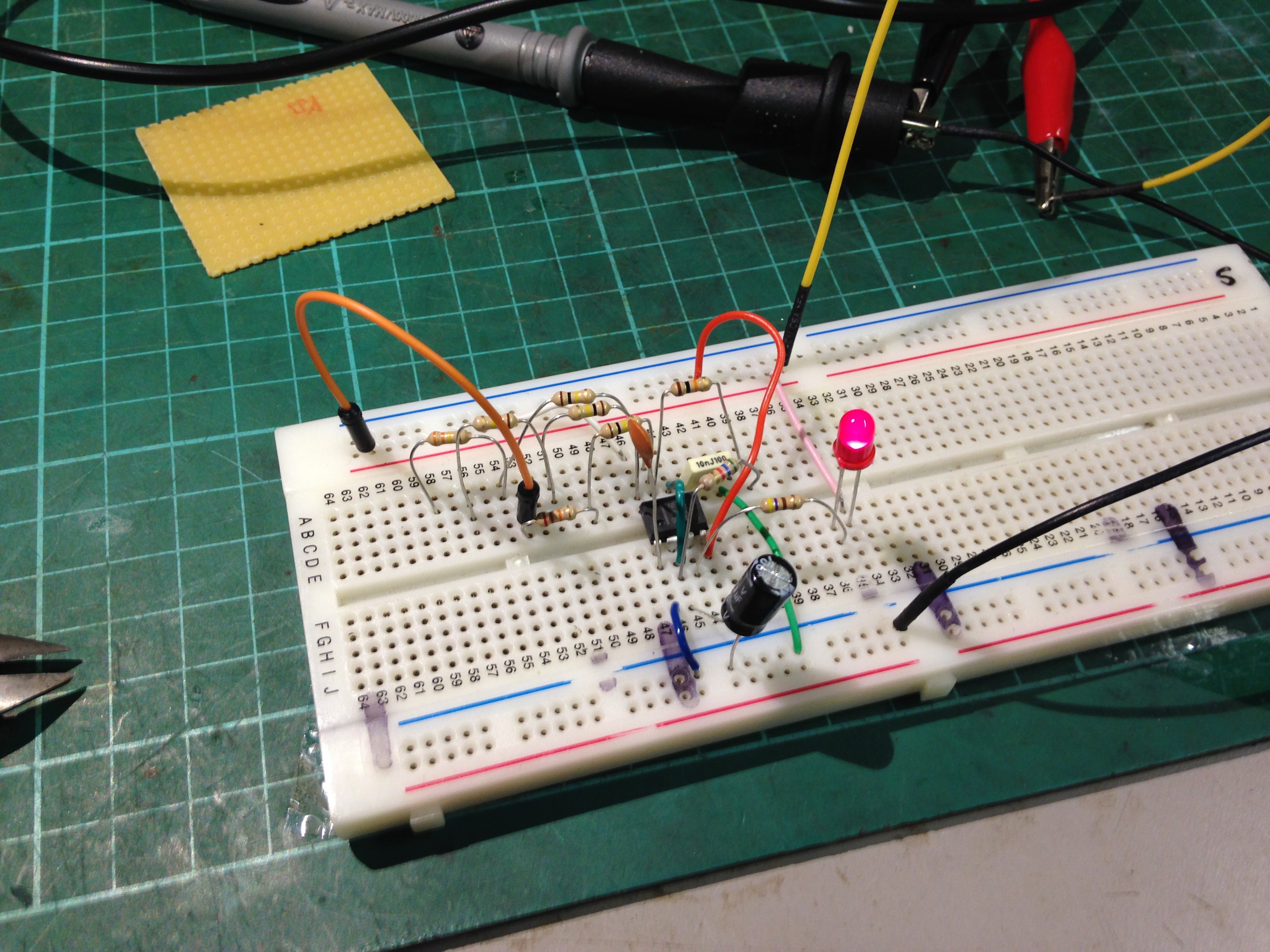
I then constructed the circuit with my calculated values onto breadboard, powered it on and gave it a try. Testing the interval with a stopwatch for each different resistor and watched the LED, it was found they were close enough to what i wanted.
| Interval required | Resistance | Recorded interval |
| 10 sec | 120k (100k+2x10k) | 10.85 sec |
| 15 sec | 200k (100k+100k) | 16.75 sec |
| 30 sec | 430k (100k+330k) | 35 sec |
So not too far out. I then decided I wanted a 5 sec interval too:
| Interval Required | Resistance | Recorded interval |
| 5 sec | 50k (2x 100k ||) | 5.19 sec |
So no problems there either.
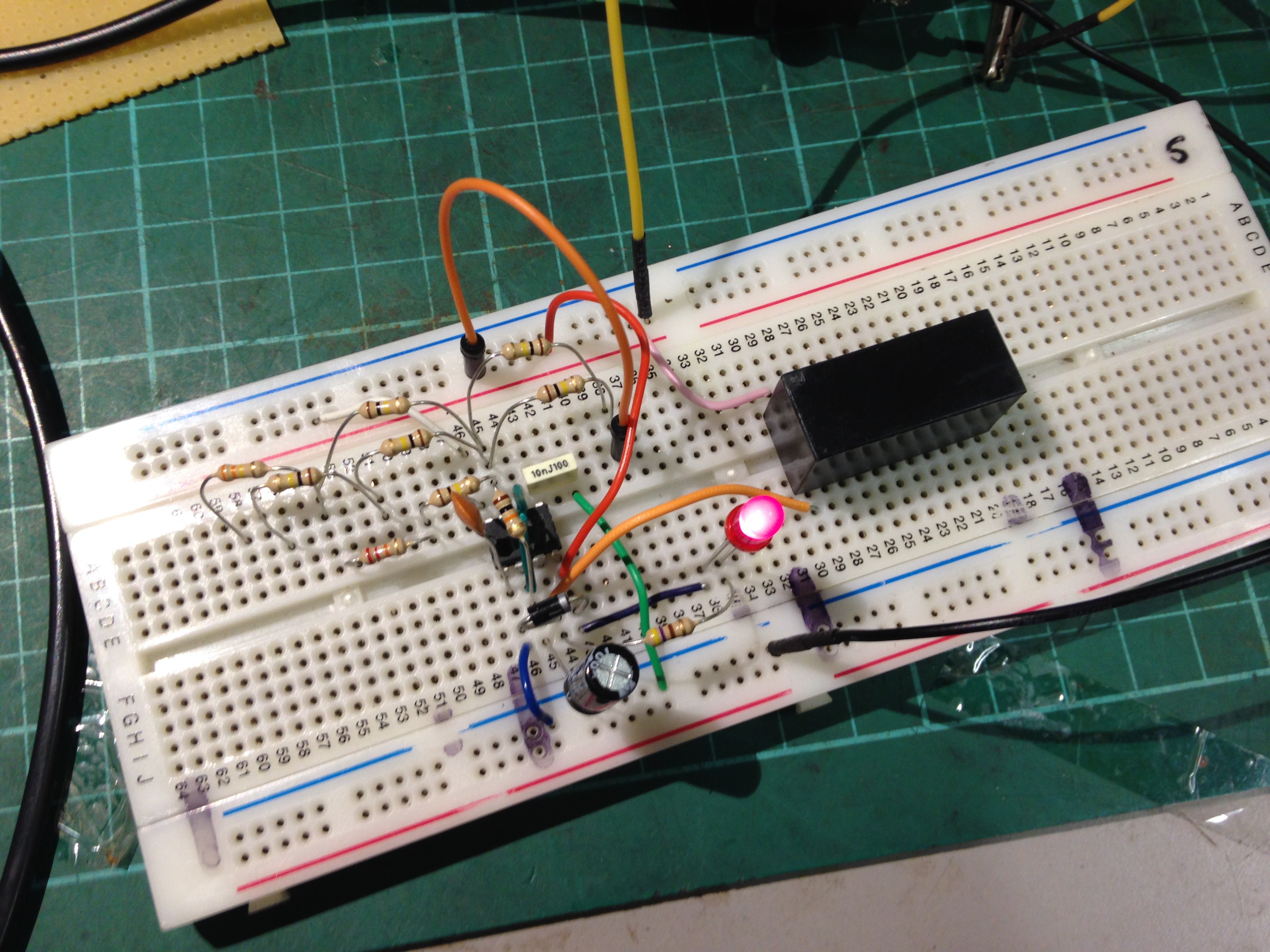
I then wanted to expand the circuit further by fitting a relay to the output. First I found a 12V relay in my parts, and then measured the current when energised through the coil: 53.2mA
I bit the bullet and hooked it up directly to the output of the 555 timer and was confident the output wouldn't suffer and it didn't, worked ok.
I then decided to remove the 4k7 making up R2 and left it as 10k, the change in on time was negligible to detect by the human eye and ear.
From this testing I had my concerns about the drive capabilities of the 555 and am considering using a PNP transistor to handle driving the relay instead of the 555 output directly.
Discussions
Become a Hackaday.io Member
Create an account to leave a comment. Already have an account? Log In.