Close
0%
0%

Intelligent Ski-Course

Autonomous buoy network for a slalom-ski course connected to your ski, deployed by simply throwing it all overboard.

Similar projects worth following
A water slalom-ski course consists of 22 buoys in total. With the course spanning 250 m, setup takes up a whole afternoon which reduces the amount of weekend left to ski. Therefore a system is devised where each buoy can simply be thrown overboard, letting it move to its allocated position. Each entity contains its own compass, GPS and micro-controller. By using 2 propellers they can autonomously move and hold their given coordinates. To facilitate communication between each buoy, a mesh network will be integrated using 2.4 GHz transceiver modules. This makes it possible for the ski as well as the boat to become part of the network, opening up a range of interactive possibilities. For example, the difficulty of the course can be set on the fly, buzzers on the buoys would indicate a successful pass and skier and boat telemetry can be stored and analysed afterwards. As an open platform, the system can even be expanded for other courses such as rowing and wake boarding.

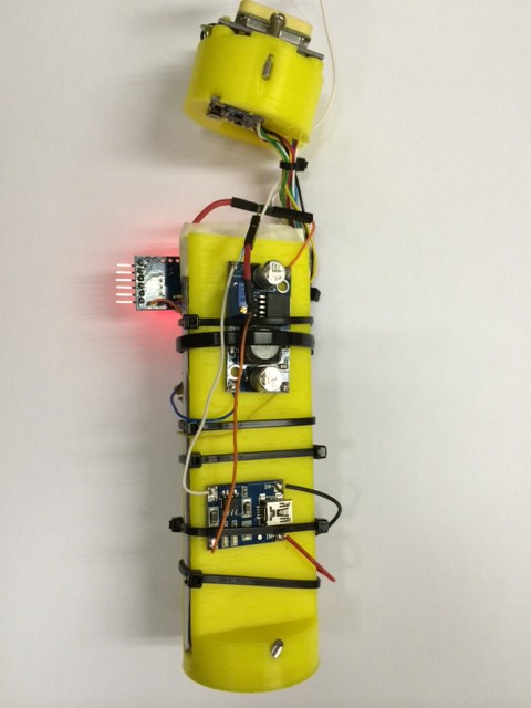
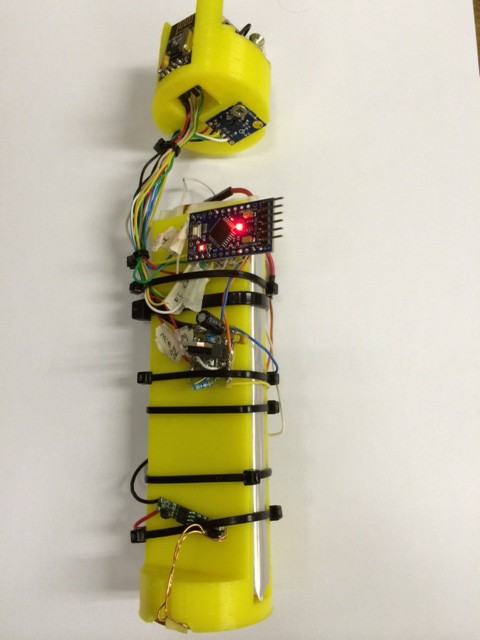
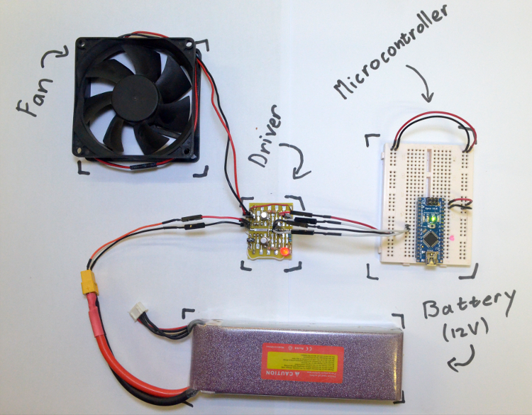
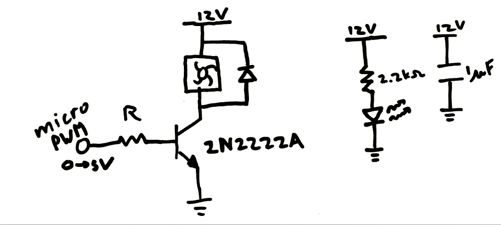
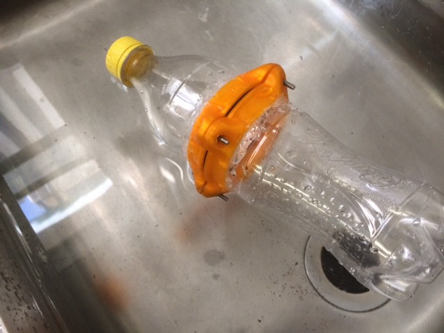
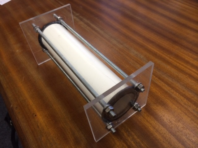
The intelligent ski-course consists of 22 buoys where every buoy is identical in both its hardware and software. This makes the project easily scalable for other uses. The course is then configured, monitored and controlled by a simple central interface located on the boat. A later addition will be a wearable add-on for the skier, which will enable him to interact with the course and vice-versa. The basic design of a ski buoy can be seen in the schematic below.

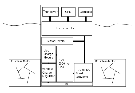
The micro-controller at the heart of the project will be responsible for keeping the buoy at a specific position and facilitating communication over the network. The GPS and compass will determine the buoy position and heading. Using this data the buoy will change its location accordingly, using 2 motors. Because the device will essentially be closed and not easily opened, wireless charging is used to replenish the battery. To make charging practical, a charging bench with multiple wireless charging bays will be used.  Solar power could be added at a later stage. For initial development, over-the-air (OTA) updates will be important. Therefore a Bluetooth module will be attached to the micro-controller. In further development OTA updates could be made available through its transceiver module. The quasi-mesh network will essentially act as a relay network to make sure packets from the boat reach their buoys and that packets from the skier reaches the boat. At a later point ultrasonic triangulation or a RTK solution could be used to increase the positional accuracy. The former of which will extensively make use of the mesh network for buoy-to-buoy communication.

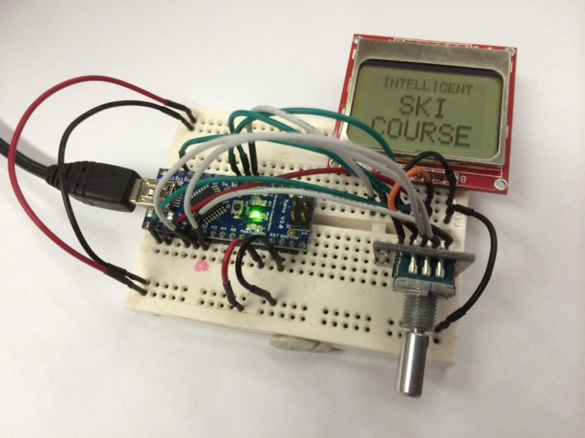
For now the goal is to build a set of 10 buoys. These buoys should be controlled by a simple device to instruct them to hold and change their position. Also, the controller should work at least 50m away from the closest buoy. Additionally, a simple charging dock will need to be built to make practical testing possible. For the community, this project will be built mostly from off-the-shelf modules and easily accessible hardware materials.


The Road-Map (Planning on finishing  up to No. 3 for the Hackaday competition):

1 - Design and test a single working buoy (With a simple user controller).

2 - Finish 3 more identical buoys.

3 - Implement networking protocols and human interface for the 4 buoy set.

4 - Build and test a 10 buoy course.

5 - Increase positional accuracy.

6 - Integrate all systems on a custom PCB to lower cost.

7 - Start with ski-sensor development.

For interest, the layout of a water slalom-ski course:

An entrance gate consisting of 2 gate buoys. The skier has to enter the course through these 2 gates. This is followed by 6 turning buoys on alternating sides of the course, which the skier needs to slalom around. Finally the course ends with an exit gate at the end. The 12 remaining buoys are used to mark out the straight lane for the boat towing the skier. 

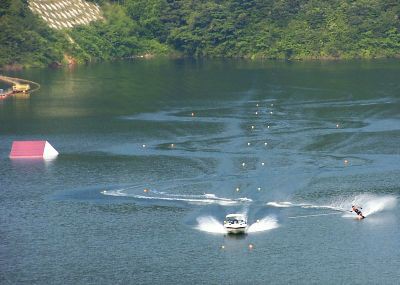
Image from Yasak Waterski Club website


Battery Life:

Consumption:

Motors: 500mA @ 6V = 3W

Tranceiver: 14mA @ 3.3V = 0.05W

GPS and Compass: 67mA @ 3.3V = 0.22W

Microcontroller: 10mA @ 5V = 0.05W

Capacity: 5000mAh @ 3.7V = 18.5Wh

Run-time: 5.58 hours

Bear in mind, this does not take into account all of the losses, for example micro-controller sourcing, etc. These calculations were also based on the assumption that both motors will be turned on 100% of the time. To be cautions, a better estimate would be about 4 hours of battery life. Its also not a good idea to run a LiPo battery down to its limit.


Possible Pitfalls and Mitigation:

- Motors to weak to drive buoy in lake conditions. (Upgrade to hobby brushless-dc motors or a bilge pump configuration, this will significantly increase cost.)

- Buoy stability under power. (Better understanding of the mechanics involved should solve this problem)

- nRF24L01+ does not currently have a mesh network implementation. A simple hierarchy network is available with RF24Network which will work, but drastically increase the chance...

Read more »

  • 1 × PVC Pipe Diameter: 50mm Thickness: 2.5mm Length: 200mm
  • 4 × Threaded rods Diameter: 6mm Length: 230mm
  • 2 × Rubber washer Inner Diameter: 40mm Outer Diameter: 60mm
  • 12 × M6 Washers
  • 12 × M6 Bolts

View all 7 components

  • 'Buoy One' Test Bed

    Hardie08/11/2014 at 17:40 0 comments

    After having all of the parts arrive, except for the new propulsion, something could be put together. Initial 3D-printed parts were used to keep most of everything organized. See the images below. The parts will be iteratively improved over the coming months. To keep things open the cad models will be made available on Github and a Thingiverse page. Extra effort was put in to start using FreeCAD to make these changeable by the community.

    This is essentially all of the electronics that will be placed in a single buoy (Except the motor drivers). The wireless charging coil can be seen at the bottom which runs to a LiPo cell charger. The LiPo itself is wedged in the middle of the 3D-printed container. The 3.7V from the LiPo is up-converted to 12V, depending on the need of the driver circuit. This is then used to feed a 5V and 3.3V regulator. These will run the following devices: a micro-controller, GPS, compass and transceiver. Notice the 2 bolts protruding out the side of the holders, these will be used lator on to fix the part on the inside of the PVC tube.

    The transceiver itself has caused a heap of grief. Basically hours of debugging, even involving some university spectrum analyser gear, only to find the transceiver was or became faulty before testing. A quick replacement got everything transmitting and receiving 100%.

    With this test-bed/cable-tie monster development has started on the communication protocol. Next post will hopefully be of the controller GUI interface. 

  • Buoy-One parts close

    Hardie08/07/2014 at 19:51 0 comments

    Buoy 1 parts are close, meaning that the first prototype can almost be assembled. In the mean time the GUI interface for the controller is basically finished and waiting for a course to talk to. Will upload a video of the GUI for some critique after contact has been made with 'Buoy One'. Here is just a nice diagram of what the controller looks like at the moment. A RF24 chip will still be added along with some other small bits.

  • Waiting on Modules

    Hardie08/05/2014 at 18:37 0 comments

    At the moment, not too much is happening in the electronic-hardware department. Currently we are waiting on NRF24L01 modules, wireless charging modules and some boost converters. The RF modules out of these are really the ones keeping us behind. Nevertheless, the all important work of building an intuitive user interface has begun. 

    The controller, or ISBController as named in the Github Rep, will be the sole means of communicating with the course. It will be responsible for sending commands, receiving alerts as well as regular updates. For now, a simple user-interface framework has been written to start populating menus. 

    In this waiting process 1 of 2 main internal plastic structures have been developed (iteration 2 in the photo). This part will be responsible for housing the GPS, compass and transceiver at the top of the PVC pipe. A simple bolt mechanism on the side allows this section to be fixed flush at the top of tube. 

  • A change of Propulsion

    Hardie08/01/2014 at 15:07 0 comments

    Thanks to comments from Jonathan Groff, I have investigated the longevity of the PC-Fan motors underwater. Story made short, 1 Fan lasted 90 minutes while the other fan started showing signs of deterioration after 180 minutes. The main cause was corrosion on the pcb of the fan. It might be possible to insulate these in a ball of grease or something similar. However after taking 1 apart, I decided the effort was futile. Therefore PC-Fan propulsion will be declared a fail (Lesson learned: Dont trust a 5 minute water test). 

    These fans were chosen for their cost (3$ each) to keep the overall buoy cost down to around (40$-50$). The options left to us are using brushless-dc motors (Used in the OpenROV project) or bilge pumps (Recommended and used by Jonathan Groff). Brushless dc motors, commonly used on multi-copters can cost around 20$ each including the ESC, which will max out the budget for 2 motors. Bilge pumps like the Rule 360 or Rule 500 come in at around 22$ each which is also too expensive for this project (See the ROSIRA for an interesting single bilge pump with solenoids solution that might be a viable option for forward and reverse functionality). However, small submersible pumps available from Banggood.com have been ordered for $2 each which are cheap enough to simply give them a try. They might not be strong enough but that will be tested once they arrive. If this does not work, the slightly more expensive options may need to be implemented.

    http://www.banggood.com/Mini-Submersible-DC-Motor-Pump-3V-120L-Or-H-Low-Noise-Max-Lift-p-87235.html

  • Propulsion Driver Board

    Hardie07/30/2014 at 18:28 0 comments

    Hardware:

    The next step is to build some simple drivers for the propulsion motors. Each buoy is propelled by 2 differentially operated PC fans. Sadly, these fans are only 1 directional. To solve this at a later stage they can be mounted back to back with another set, or be totally replaced by a different type of motor and propeller. Nevertheless, they are cheap and available all around the world in standard sizes. A simple bathtub test, with a 60x15mm fan mounted on a bottle, showed some promising performance.

    Because each fan is simply 1 directional, there is no need for an H-bridge. Each motor can be driven using a simple transistor as an on and off switch. To enable a manner of thrust control, each of these switches will be driven with PWM.

    For the switch, a BJT or Mosfet can be used. Due to the availability, a BJT was chosen in an NPN configuration. This kept the maths simple and the micro-controller safe. Additionally a free-wheeling diode was added over the fan to remove those nasty inductive-switching currents. Finally to take the edge off of things a 1uF capacitor was placed over the 12V rails close to the switching transistors.

    Reading the datasheet, the transistor-gain (Beta) is about a 100 at our conditions. To make sure the PC Fan is fully turned on, I_CE was chosen at 200mA. Therefore, the base current (I_BE) needed to be 2mA. Using a current loop from the PWM pin, a value for R was calculated:

    R*I_BE + 0.7 = 5

    R = 2.2 kOhm

    A darlington pair can be used to minimise the micro-controller sourced current, but this is probably not necessary. At saturation the NPN transistor will have a V_CE voltage of about 0.3V. Taking our designed 200mA, a total of 0.06W of heat will be generated in the transistor. Using the thermal resistance for a TO-18 case (300 degrees/Watt) the junction temperature can be calculated.

    25 + 300*0.06 = 43

    This is well below the absolute maximum ratings. Running for several hours, the ambient temperature inside the enclosure will rise. This could be experimentally tested using a temperature sensor during the initial ‘wet runs’. Below is an image of the prototype driver board with its 2 PC-fan drivers. 

    Software:

    A simple piece of driver code is added to mask the PWM functions and make the overall code more abstract. This code has 5 functions which are self-explanatory. This will be the first software for this project. The github link can be found at the end of this post. For prototyping an Arduino Nano V3 was used, this might change to a pro-mini later on to minimise BOM cost.

    void setupMotors(int leftMotor,int rightMotor)

    void setLeftThrust(int thrust)

    void setRightThrust(int thrust)

    int getLeftThrust()

    int getRightThrust()

    Additional to the motor-driver file, a pin-definition header file has also been added. This should keep things organised as the code grows.

    Github Repository:

    https://github.com/hardiepiennar/ISBuoy

  • Waterproof Electronic Enclosure

    Hardie07/28/2014 at 15:26 0 comments

    The first step in constructing an autonomous buoy is to design a suitable-rugged enclosure for the electronics. This enclosure should be easily replicated by anyone anywhere at a low cost point. Here are three possibilities:

    A 500ml Coke bottle cut in half to add the electronics. The bottle would then be resealed with 3D-printed brackets and some silicone. This would enable anyone to construct the enclosure with access to a 3D-printer and a bottle of coke. Below is a photo of the attempt. It was found that sealing the 3D-printed parts to the bottle proved difficult and did not prove to be rugged enough. 

    A plastic honey-jar available from a nearby factory. These jars come in very cheap and are already equipped with a screw-able lid. However, these jars may not be available as a standard across the world and was immediately discarded.

    Image from http://www.plic.co.za/

    The final design which has been chosen for the project is a PVC pipe sealed ends.  PVC is available everywhere in standard sizes and Perspex can easily be obtained. In this design a PVC pipe is sandwiched between Perspex using 4 threaded rods. This enclosure proved to be extremely rugged and 100 percent waterproof. 

    This was simply a waterproof test model. The final model would have rounded Perspex ends which will be manufactured on a CNC machine. The only problem with this design is the effort needed to open the container by unscrewing 4 bolts. This will affect the design of the electronics. Wireless charging and over the air programming will need to be implemented to make the design practical. 

    The bill of materials is as follows:

    4 x Threaded rods (M6 Length: 230mm)

    1 x PVC pipe (Diameter: 50mm Thickness: 2.5mm Length: 200mm)

    2 x Rubber washers

    2 x Perspex ends

    12 x nuts and washers (M6)

    Silicon sealant to seal washers to PVC

View all 6 project logs

Enjoy this project?

Share

Discussions

jcochrane007 wrote 03/14/2019 at 01:40 point

I see that this project has been silent for five years, but I am interested in reviving it.  I will be moving to a public lake in South Carolina later this year and this would be an ideal solution.  If anyone else is interested please let me know.

  Are you sure? yes | no

Chris Zalegowski wrote 02/10/2020 at 15:39 point

I am interested in the success of this project. 

  Are you sure? yes | no

davidgree wrote 08/13/2014 at 16:49 point
The slalom course turn buoy's need to be placed with accuracy of less than a foot. In addition skiers do ski in variable wind conditions. Does gps technology allow such accuracies?

  Are you sure? yes | no

Hardie wrote 08/13/2014 at 17:03 point
This course is definitely not designed to replace fixed courses. This is a course for the public lake skier like me, with no access to a real course. The accuracy of GPS is limited, but will still deliver a fun course to get young skiers into carving. In the long run RTK can be used for cm (or inch) level accuracy. Also, it might possible to use sonar ranging under water to determine precise distances. In this case the GPS will only be used for baseline positioning. The design will be completely opensource, therefore anyone with a better solution could try and implement it. For the moment I am focusing my efforts on a GPS controlled course only (Keeping it simple, for now).

  Are you sure? yes | no

jpwhit wrote 08/11/2014 at 15:36 point
Apparently a fair number of folks have worked on a similar concept in the past. I worked on essentially the same thing a few years back, but it became clear it was going to take more time than I was willing to spend to get it to a workable state. I do think it's possible, but it ends up being a very challenging project. I would recommend that you work on the physical buoy and propulsion design early in the process.

Getting a reasonably controllable buoy in real life lake conditions is pretty challenging. For example, with the design you have proposed at the moment with the motors near the bottom, the whole buoy is going to tilt over on it's side when you try to move in one direction. It'll rotate ok, but will be problematic trying to propel itself in one direction. I came to the conclusion that the buoy would have to actively stabilized on all three dimensions. Keeping the rotational orientation of the buoy, so you can actively navigate the way you want, also turns out to be quite challenging.

Good luck, and I wish I had the time to help, but am too involved in other projects at the moment.

  Are you sure? yes | no

Hardie wrote 08/11/2014 at 19:36 point
I will definitely focus on the propulsion, just waiting for the new motors to arrive. In the mean time I am trying to build a base system which should make testing easier, eg. remote control and a telemetry link. Thanks for the heads-up on the stability issues. If you happened to write anything up on the web, could you share?

  Are you sure? yes | no

Fogmanbindings wrote 08/10/2014 at 14:15 point
Exciting idea. I would us guess you should use the Goode Bubble buoy idea instead of a buoy mounted on top. The buoy is a sheath type of buoy that could act as a "diving bell" for your electronics so that they would be less exposed to direct contact with water. Also keep in mind that buoy height and softness are very important to the safety of the skier. I would also put some programming in that if a buoy goes off line for some reason, the boat is notified. If a buoy were to shut off and float wide as a skier was coming in to it, the results could be dangerous. Keep up the good work

  Are you sure? yes | no

Hardie wrote 08/11/2014 at 07:56 point
The safety aspect is a bit of concern, hitting a piece of PVC at skiing speed would not be ideal. The Bubble Buoy idea would be great, except the GPS and tranceiver wont work below the water surface. There might be some configuration where the electronics can be held above the surface while maintaining some of the safety the Bubble Buoy provides. At this point I will just be focussing on getting the Proof of Concept going. So I will risk myself for the time being. Thanks for the useful recommendation.

  Are you sure? yes | no

Hardie wrote 08/09/2014 at 07:39 point
Thanks Dan C for finding this patent. http://www.freepatentsonline.com/y2010/0087110.html

It is scarily similar to this project. Not sure how opensource/openhardware coexists with patents.

They do however miss one of the key objectives of the intelligent course. Exploiting the connectedness to create a platform for future additions. This includes a sensor on the ski so that the course can react to you. Also camera equipment can be automated for tracking and triggering on certain events through a pass. Similar to how android created a platform for apps, the course could be a platform for some interesting ski-gear.

  Are you sure? yes | no

Dan C wrote 08/10/2014 at 12:47 point
I was reading about this concept on a waterskiing forum awhile back and someone looked into the patent further and saw that it was abanonded in 2011.

Really interested to see how this project goes for you. I'd be very interested in this if you are able to get it to market someday.

  Are you sure? yes | no

Caylan wrote 08/08/2014 at 15:18 point
I am a slalom skier and independent mobile app developer living in Winona, MN. My speciality is BTLE (Bluetooth SMART) sensor integration for large corporations. Let me know if I can be of use for this project.

  Are you sure? yes | no

Hardie wrote 08/08/2014 at 17:53 point
BLTE would be great on this project. They are however slightly pricey in breakout form, from what I have seen. However, a single BTLE on the controller end would be great, this would open up many possibilities for mobile interaction. In the simplest form, an app that controls the course (Currently done on the small lcd seen on the build logs) . Ideally it would be great to remove the whole controller board and run the course off of a mobile app. This will however only be investigated at a later stage.

If you are interested, some mobile app development could be done to interface to the controller (located on the boat) through BTLE . At first it could serve simply as an alternative interface for the sake of keeping things simple. This would definitely set an awesome basis for development at a stage where features can be added.

Let me know what your ideas are, the GitHub is their if you want to start with some code. You are welcome to contact me by email. NameSurname@gmail.com

  Are you sure? yes | no

stevenaschnitzer wrote 08/08/2014 at 12:26 point
I heard about this project years ago. It may already exist! I was sworn to secrecy. Send me an email to discuss; sschnitz at mindspring dot com

  Are you sure? yes | no

Hardie wrote 08/08/2014 at 13:09 point
Years ago? Should have been finished by now. I have searched for such a solution on the net with no success. Therefore this project is completely opensource. Meaning anyone with some electronic experience will be able to construct one for their local club.

  Are you sure? yes | no

Drifter wrote 08/02/2014 at 12:03 point
Good news..... I did some research around the web and the "Navspark" gps board appears to provide cm accuracy for around $22 a piece, and is arduino friendly.

  Are you sure? yes | no

Hardie wrote 08/02/2014 at 12:13 point
An RTK solution will definitely work, especially at this price point. I will keep track of NavSpark. I am currently waiting on NEOV6 GPS modules that are 13$ each. I am sure that when the initial project works, this will be a perfect GPS replacement. Thanks alot.

  Are you sure? yes | no

Drifter wrote 08/01/2014 at 21:39 point
Absolutely brilliant concept.
I'm curious about how to do the gps side of things. Affordable gps modules appear to have an accuracy of a few metres, clearly not enough for a slalom course. Is there a solution for this other than waiting for the inevitable price drop over time?

Being able to toss the buoys out of the boat and have a instant course would have to the coolest waterski thing ever!

  Are you sure? yes | no

Hardie wrote 08/02/2014 at 08:40 point
It is definitly going to be a fun project to test. At this moment my goal is to get the course communicating and roughly positioned using the gps. I dont know too much abut the mechanics behind GPS, but I am hoping the relative accuracy between the gps units, in the same location, would not be too far off. However, if we happen to end up with a wonky course, I have a plan to use sonic triangulation under water. This might give us more accurate distances between nodes while using the the gps only as a base line. This idea however might be a project on its own, but it does give some hope. Not sure what accuracy is achieveable with sound waves under water, but the propogation speed might be in our favor.

  Are you sure? yes | no

J Groff wrote 07/30/2014 at 19:19 point
Nice project but you are going to face some serious issues with those impellers. Issues such as possibly immediate failure. I would suggest replacing those 2 fans with 4 small bilge pumps to give you full forward/reverse thrust for effective station keeping. Your driver circuit should be changed to a MOSFET with logic level gate and a PC123 optoisolator between PWM and gate resistor (x4). its also a good idea to put a gate-to-source 1k resistor to prevent floating gate. Good luck!

  Are you sure? yes | no

Hardie wrote 07/31/2014 at 08:19 point
Jonathan thanks for the comment. They are definitely one of the unknown parts of this project. I have no experience with bilge pumps and how standard they are. My main reason for choosing the fans are that they are very standard and accesible across the world. However, their performance underwater might not be that standard . because of your comment I will be running a long term wet test on the motors. A simple script will cycle each motor from 0% to 50% to 100% each minute and see if they survive.

A slalom-ski course is usually only used in glassy-still water. Therefore, almost no outside forces. In this case the fans should work. However a forward and reverse capability would make things easier. Could you recommend some standard bilge pumps? My estimate for each buoy at this moment is about $40-$50 each. 2 fans come in at 6$. Just a quick google, and I found a 2$ RC pump which might do the trick.
http://www.banggood.com/Mini-Submersible-DC-Motor-Pump-3V-120L-Or-H-Low-Noise-Max-Lift-p-87235.html

  Are you sure? yes | no

J Groff wrote 07/31/2014 at 16:24 point
Hi Hardie. The old bilge pump is a pretty well known quantity and its designed for long term submersion and goes without saying, rough doodie. About the smallest is 500gph usually about $20:http://www.go2marine.com/item/44142/rule-non-automatic-submersible-pumps-12-24-and-32-volt-dc-25d.html you can see the size related to the 3/4 in outlet. What many hobby submariners do is remove the impeller and housing and replace it with a model boat prop as centrifugal impellers are less efficient. They do however, not get clogged easily or hung up on things which is why I used them on the ROSIRA. I suggested 4 pumps as that would be the easiest engineering wise but for a more compact system use 4 of those Adafruit fluid solenoids ($7) waterproofed as I did in the ROSIRA. This is one of the assemblies I use for that sub. Only one bilge pump is then needed and you control the flow by turning on and off the solenoids. Those Adafruit ones work at low pressure which many diaphragm ones dont so theyre special.
I realize it starts as a flat lake but then a bunch of guys are nads out skiing over all of them so I believe your going to have to have a way to constantly re-align them in relation to each other and the course. That will be your biggest challenge. Plus, how cool would it be to just toss them all off the dock and have them swim out and set themselves up! You would draw the course in an app overlaying the sat image of the lake and it would be georeferenced and uploaded to all the 'bots. You could have people pay you to have them form up ads at the end of the ski event or something too!

  Are you sure? yes | no

visualkev wrote 07/28/2014 at 20:03 point
A possible solution for water proofing the electronics is to encapsulate the circuitry in a, possibly silicone, compound or something like this: http://www.ebay.com/itm/EPOXY-RESIN-CIRCUIT-BOARD-POTTING-COMPOUND-NON-CONDUCTIVE-WATERPROOFING-48OZ-/310186942108?pt=LH_DefaultDomain_0&hash=item4838951e9c

I'm not sure if there is a compound that's less dense than water, but that seems like it would be optimal to mold your devices in, making integrated buoyancy.

This approach is only useful once the hardware design is set, so for your production devices.

  Are you sure? yes | no

Hardie wrote 07/29/2014 at 06:42 point
Will definitely give this a try when the hardware is finalised. I have seen it being used on outboard-engine electronics, not the easiest thing to remove. Would be a bonus if it is less dense than water.

  Are you sure? yes | no

Similar Projects

Does this project spark your interest?

Become a member to follow this project and never miss any updates