 Hardie
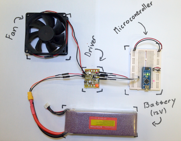
Hardware:
The next step is to build some simple drivers for the propulsion motors. Each buoy is propelled by 2 differentially operated PC fans. Sadly, these fans are only 1 directional. To solve this at a later stage they can be mounted back to back with another set, or be totally replaced by a different type of motor and propeller. Nevertheless, they are cheap and available all around the world in standard sizes. A simple bathtub test, with a 60x15mm fan mounted on a bottle, showed some promising performance.
Because each fan is simply 1 directional, there is no need for an H-bridge. Each motor can be driven using a simple transistor as an on and off switch. To enable a manner of thrust control, each of these switches will be driven with PWM.
For the switch, a BJT or Mosfet can be used. Due to the availability, a BJT was chosen in an NPN configuration. This kept the maths simple and the micro-controller safe. Additionally a free-wheeling diode was added over the fan to remove those nasty inductive-switching currents. Finally to take the edge off of things a 1uF capacitor was placed over the 12V rails close to the switching transistors.
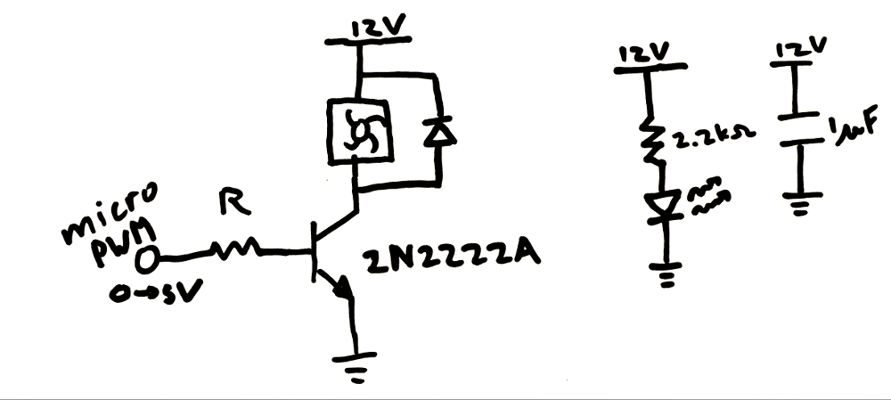
Reading the datasheet, the transistor-gain (Beta) is about a 100 at our conditions. To make sure the PC Fan is fully turned on, I_CE was chosen at 200mA. Therefore, the base current (I_BE) needed to be 2mA. Using a current loop from the PWM pin, a value for R was calculated:
R*I_BE + 0.7 = 5
R = 2.2 kOhm
A darlington pair can be used to minimise the micro-controller sourced current, but this is probably not necessary. At saturation the NPN transistor will have a V_CE voltage of about 0.3V. Taking our designed 200mA, a total of 0.06W of heat will be generated in the transistor. Using the thermal resistance for a TO-18 case (300 degrees/Watt) the junction temperature can be calculated.
25 + 300*0.06 = 43
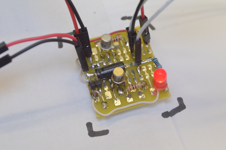
This is well below the absolute maximum ratings. Running for several hours, the ambient temperature inside the enclosure will rise. This could be experimentally tested using a temperature sensor during the initial ‘wet runs’. Below is an image of the prototype driver board with its 2 PC-fan drivers.
Software:
A simple piece of driver code is added to mask the PWM functions and make the overall code more abstract. This code has 5 functions which are self-explanatory. This will be the first software for this project. The github link can be found at the end of this post. For prototyping an Arduino Nano V3 was used, this might change to a pro-mini later on to minimise BOM cost.
void setupMotors(int leftMotor,int rightMotor)
void setLeftThrust(int thrust)
void setRightThrust(int thrust)
int getLeftThrust()
int getRightThrust()
Additional to the motor-driver file, a pin-definition header file has also been added. This should keep things organised as the code grows.
Github Repository:
Discussions
Become a Hackaday.io Member
Create an account to leave a comment. Already have an account? Log In.