Close
0%
0%

Thotcon 0x8 Badge

Details on the badge for Thotcon 0x8 (2017)

Similar projects worth following
This year's Thotcon brought another excellent electronic badge. Like the 0x6 badge I reviewed here previously, this badge is once again powered by an Atmega32u4 micro controller, the same one used in the Arduino Leonardo. On board it has 4 x RGB Neopixel LEDs, 3 potentiometers, a micro USB port, and 2 x CR2032 coin cell holders. The badge was designed by the guys at Workshop 88.

The badge's stock firmware is a maze puzzle game in which you need to navigate an 8 x 8 x 8 cube. You manipulate your position in the maze with the 3 potentiometers. The left most pot controls what layer (0, 2 - 8) of the cube you are in (Z axis), the center pot controls your X axis position (A - F, X, Z), and the right most pot controls your Y axis position (1 - 8).

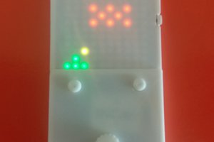
The game can be visualized in two ways. The first is with the 4 LEDs on the badge, which represent paths and objects in the maze to the North, South, East and West of your current grid location. A white LED represents an open pathway, a purple LED represents a portal (aka Z axis pathway up to the next layer of the cube), and an orange LED represents a key you need to collect in the maze. If you run into a wall, all LEDs light up red, meaning you are dead and need to start over. In my "compass" image in the gallery, I am at Layer 0, at coordinates X, 7. You can seen a purple LED to the north and white LED to the south.

The second way to navigate the maze is via the badge's serial console, available via the USB port. Remove the coin cell batteries from the badge before connecting a USB cable, otherwise you will only get USB errors on the PC. Set the dials to 0, X and 8, otherwise the badge will often appear to do nothing when plugged in, and might not even show up as a serial device. You may need to reset the board a few times with the "boot" button on the back. After connecting to the virtual COM port at 9600 baud 8-N-1, it displays a "tesserHack" menu with M for "Map view" and H for "Help menu" options. Map view shows your current X, Y position and where the open pathways are. Press R to refresh the map as you twist the pots. The screenshot of putty displaying the maze also shows my location at Layer 0, Origin X 7.

  • Badge hacking: update

    Gigawatts05/12/2017 at 03:00 0 comments

    After a note from [Scott Fish] posting a comment to the hackaday article, I went back and flashed a verified working version of the original badge firmware (properly dumped from a friend's badge) back to my badge.

    It seems Scott was having trouble getting the badge to reboot to a bootloader so that it could be overwritten with custom firmware from the Arduino IDE. He was just getting the error:

    Connecting to programmer: .avrdude: butterfly_recv(): programmer is not responding

    I too ran into the same error via both the Arduino IDE and avrdude command line. This tells me the badge either does not have a bootloader, or something is preventing it from entering the bootloader properly when reset.

    This means the only way to write custom firmware to the badge is to first burn the Arduino bootloader to the onboard Atmega32u4. That process requires an external AVR programmer of some sort. I personally used the buspirate. Here are the steps I had to take to get the badge to behave like a regular Arduino Leonardo, programmable via USB.

    • Solder a 2x3 male pin header to the badge's ICSP port. This is just above the center pot, with pin 1 being the lower left corner. There is a small _ next to this pin to make it obvious.
    • Don't make the mistake I made and try to just hold 6 pins to the pads. This is how I corrupted my firmware to begin with.
    • Connect your AVR programmer to the ICSP port
    • Open up the Arduino IDE, open the "Tools" menu, and change the following:
      • Board: Arduino Leonardo
      • Port: [select the COM / tty serial port of your AVR programmer]
      • Programmer: [select the type of AVR programmer you have]
    • Open up the example "BareMinimum" sketch from the "File > Examples > 01.Basics" sub menu
    • Click "Burn Bootloader"
    • Once complete, disconnect your AVR programmer and ICSP cable
    • Plug the badge in via USB

    If everything went well, you should have an Arduino Leonardo show up in your IDE serial port list. Now you should be able to upload my example RGB sketch, or write your own.

    Good luck, and I hope this helps clear up any confusion around re-purposing the badge for custom firmware.

  • Badge hacking

    Gigawatts05/08/2017 at 01:52 0 comments

    The badge can be easily reprogrammed using the Arduino IDE as an "Arduino Leonardo" target. In my case, I accidentally erased the flash of the atmega32u4 while trying to dump the stock firmware, so I used a buspirate as an ISP to burn the arduino bootloader back on to the badge via the broken out ICSP header. After a few rounds of guessing at pin numbers, I mapped all the pot and LED pins out as follows:

    Arduino PinConnected to
    A2Left potentiometer
    A1Cener potentiometer
    A0Right potentiometer
    11Neopixels
    • The first neopixel (index 0) is the bottom most LED.
    • Each pot turned fully counterclockwise provides a value of 1023, and 0 when fully clockwise

    I wrote a quick demo sketch where each potentiometer controls the brightness of Red, Green, and Blue respectively. The first 3 LEDs show each individual color brightness and the 4th LED displays all 3 color channels at once, mixing to different colors depending on the brightness of each color channel. The result is showed in the first image in my project gallery. I have shared the code to this sketch on github, also linked from the main project page.

View all 2 project logs

Enjoy this project?

Share

Discussions

Gigawatts wrote 05/12/2017 at 01:19 point

[Reply to steveor, for some reason it wouldn't let me reply in-line]

My advice would be to solder on the 2x3 ICSP header and use something like a buspirate or any other avr programmer compatible with avrdude. Don't do what I did and just try to hold the pin headers in place for ~40 seconds (without proper pogo pins) while it dumps. That is how I accidentally erased my flash ;-)

Then you should be able to run commands like the below. m32u4 is the chip type on the badge, buspirate is the programmer I am using, and /dev/ttyUSB0 is the serial device my buspirate showed up as. Google search for avrdude flash dump, lots of great resources out there. Here is the first link I just turned up that explains it pretty well   http://www.evilmadscientist.com/2011/avr-basics-reading-and-writing-flash-contents/

## dumps the flash to a raw hex file

avrdude -p m32u4 -c buspirate -P /dev/ttyUSB0 -U flash:r:thot8-flash.hex:r

## dumps the eeprom to a raw hex file

avrdude -p m32u4 -c buspirate -P /dev/ttyUSB0 -U eeprom:r:thot8-eeprom.hex:r

  Are you sure? yes | no

steveor wrote 05/09/2017 at 00:34 point

Hi Ken.  I successfully connected my badge but never figured out how to get the token. The maze just sent me to 8x8 and I assume the point was to go back to 0x8 infinitely. I was curious if you knew how to get into the operating system like the group that hacked into it and received a prize for their efforts.

  Are you sure? yes | no

Gigawatts wrote 05/09/2017 at 01:00 point

I believe what the winning group did was extract the firmware and decompile it. There were also multiple firmware versions available from workshop 88, at least 4 that I know of. The first few contained no "keys" to collect, but version 4 did. I was attempting to extract version 4 from my badge when I accidentally erased the whole thing, haha. 

That's when I decided to write this up and show an example custom firmware.

  Are you sure? yes | no

steveor wrote 05/09/2017 at 01:05 point

Are you aware of any tutorials explaining how to extract the firmware?

  Are you sure? yes | no

Similar Projects

Does this project spark your interest?

Become a member to follow this project and never miss any updates