 Chris.deerleg
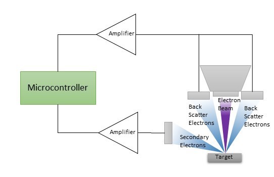
The image above gives an overview how the electrons are collected and detected. The incoming electron beam triggers two types of electrons: the Back Scatter Electrons (BSE), which fly backwards along the beam and the Secondary Electrons (SE), which stay close to the target and don't move. Charged plates are located both above and alongside the target. The image below shows how a picture looks with BSE compared to SE.

I expect that the BSE and the SE current to be measured will be quite low. Therefore, I had to look for an amplifier with a very low leakage current of the inputs. I am glad that I now found femto ampere amplifiers for an affordable price. The LMP7721 from Texas Instruments and the ADA4530 from Analog devices. Both companies have several application notes which explain how to use these amplifiers.

Above is shown the whole schematic I created to measure the BSE and SE. In the next paragraphs I explain each part in more detail:
A: This section shows the Femto ampere amplifier. The opamp is configured as a non-inverted amplifier. The reason is that with a configuration as a inverted amplifier it is hard to get a broad band width. For example a 1 GOhm resistor with a 1p capacitor in parallel would result in a cutoff frequency of 160Hz (f=1/(2*PI*1G*1p). Further The amplification is set to 2.48 (8.2k/3.3k=2.48) for stay in a comfortable area of the GBW (Gain Band Width) of the opamp. The 10p capacitor set the low pass cutoff frequency to 1.94MHz (f=1/(2*PI*8.3k*10pF). The virtual ground (VirGnd=3.3V/2=1.65V) is set to the half supply voltage of the micro controller. The applied VirGnd voltage appear at the +input of the opamp and make it possible to measure even negative current with just a single supply of the opamp. The 6k8 resistor in the input line limits the current in the case of activating the opamp internal ESD dioses. The 6k8 builds with the opamp internal capacity a low pass with a cutoff frequency of 2.12MHz ((f=1/(2*PI*6k8*11pF)) .
B: This section shows the secondary amplifier. The Max4450 is a high speed opamp and has a band width of 175MHz. This make it possible to get amplification of 14,4 (Av=56k/3.9k) at 1MHz. The high bais current of 6.5µA requires to configure the opamp as a inverted amplifier, because in the configuration as non-inverted amplifier is it challenging to get a stable virtual ground. The low pass cutoff frequency of each opamp stage is set 2.4MHz ((f=1/(2*PI*56k*1.2pF)) . The 10µF input line creates a high pass with a cutoff frequency of 0.27Hz (f=1/(2*PI*{56k+3.9k}*10µF). This high pass blocks the DC voltage of each previous stage.
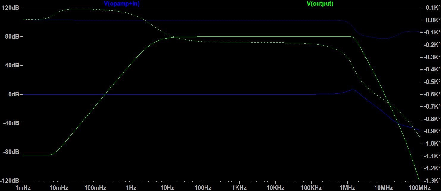
The image above shows a bode plot over the whole amplifiers. The blue line is the signal at the +Input at the LMP7721 of section A and the green line is the output at the last MAX4450 amplifier of section B. The plot illustrate the whole schematic creates a amplification of 80dB. This mean that a 1 Femto ampere make a output of 10mV (U=I*R*Av=1fA*1G*10000).
C: This section shows the guard amplifier. For measuring Femto ampere is a addition shielding required, which is in chapter 8.1.1 of datasheet of the LMP7721 described. The approach for this shielding is to surround the high impedance input of the femto ampere amplifier with a signal which has a equal potential but lower impedance. Analog Devices gives in the chapter Layout Guidelines of datasheet ADA4530 a good overview. The actual guard amplifier is a non-inverting amplifier connected to the -input of the Femto ampera amplifier.
D: This section are just symbolizing the power supplies . The 5V power supply is for the amplifiers and the 3.3V for the virtual grounds.
E: This section shows the generation of the virtual ground for the secondary amplifier. The resistors 100 times lower as the resistors for the secondary amplifier to make virtual ground insensitive. Furthermore the 10µF capaciter create a low pass cutoff frequencey of 160Hz ( f=1/(2*PI*100*10µF).
F: This section shows the generation of the virtual ground for the Femto ampere amplifier. The resistors 10 times lower as the resistors for the Femto ampere amplifier to make virtual ground insensitive. Furthermore the 10µF capaciter create a low pass cutoff frequencey of 160Hz ( f=1/(2*PI*100*10µF).
G: This section shows the generation of the virtual ground for the secondary amplifier. The resistors 100 times lower as the resistors for the secondary amplifier to make virtual ground insensitive. Furthermore the 10µF capaciter create a low pass cutoff frequencey of 160Hz ( f=1/(2*PI*100*10µF).
H: This section symbolizing the current for the detectors.
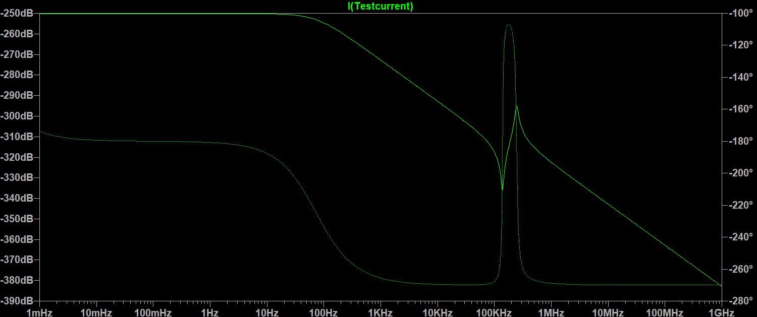
G: This section shows a schematic to create a test current. The image below show abode bode plot of the test current through 470M resistor in line with the +input of the opamp LMP7721.
Discussions
Become a Hackaday.io Member
Create an account to leave a comment. Already have an account? Log In.