Close
0%
0%

Staircane

The Staircane will enable people who need a walker to easily climb up and down stairs of any size.

jimJim
Similar projects worth following
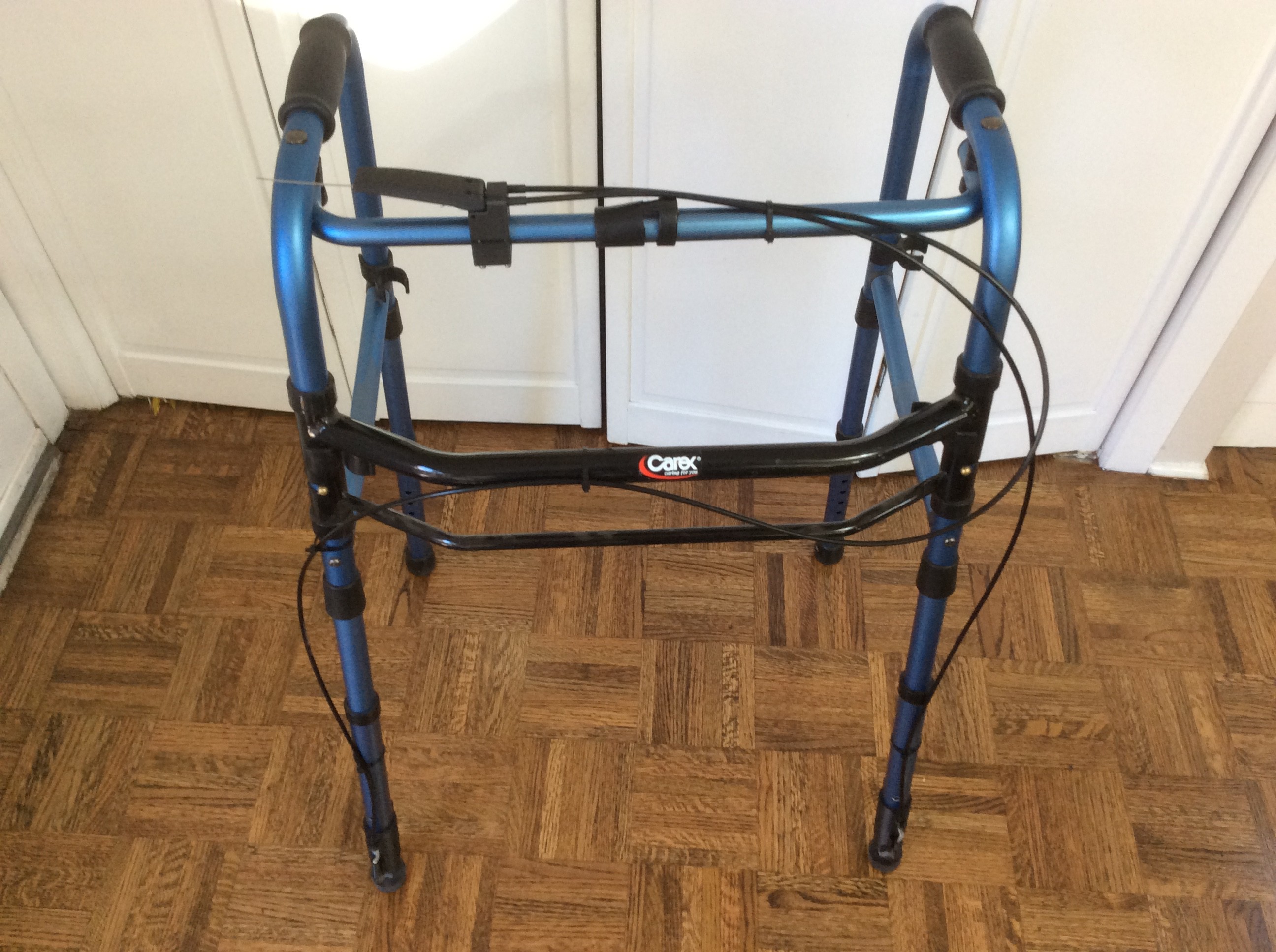
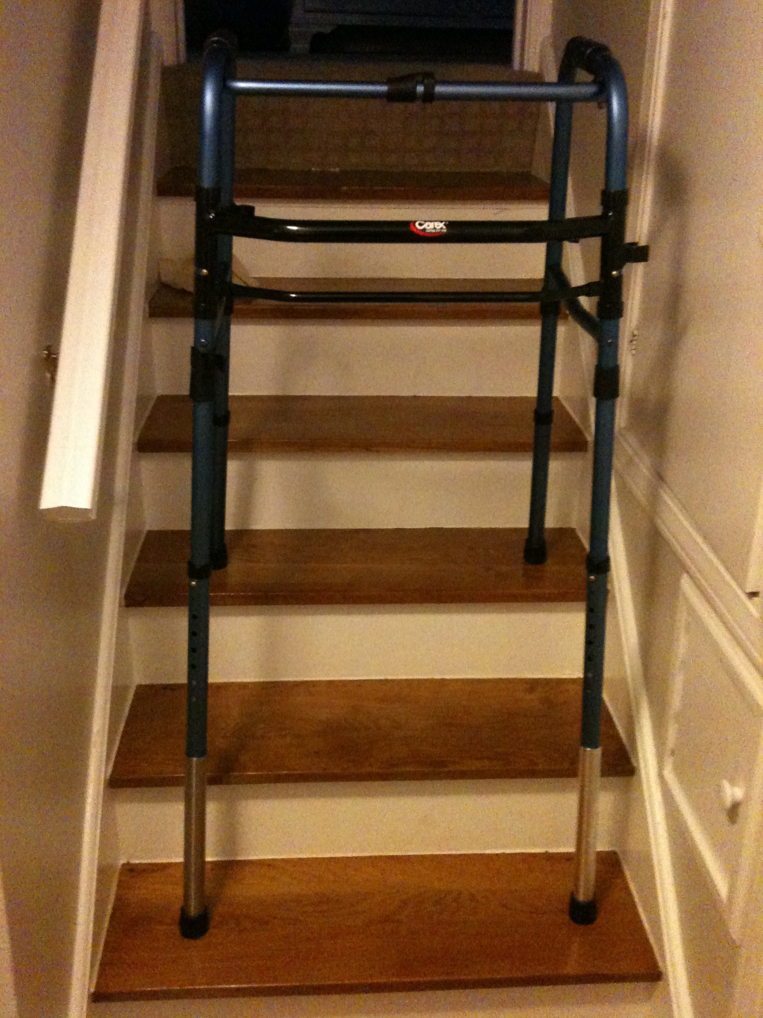
Our Aunt lives in a house that she has owned for 50 years. As she ages, it is becoming difficult for her to climb stairs. To help her age in place, we enhanced the standard walker design with adjustable-length front legs so that it can be used on any stair geometry.

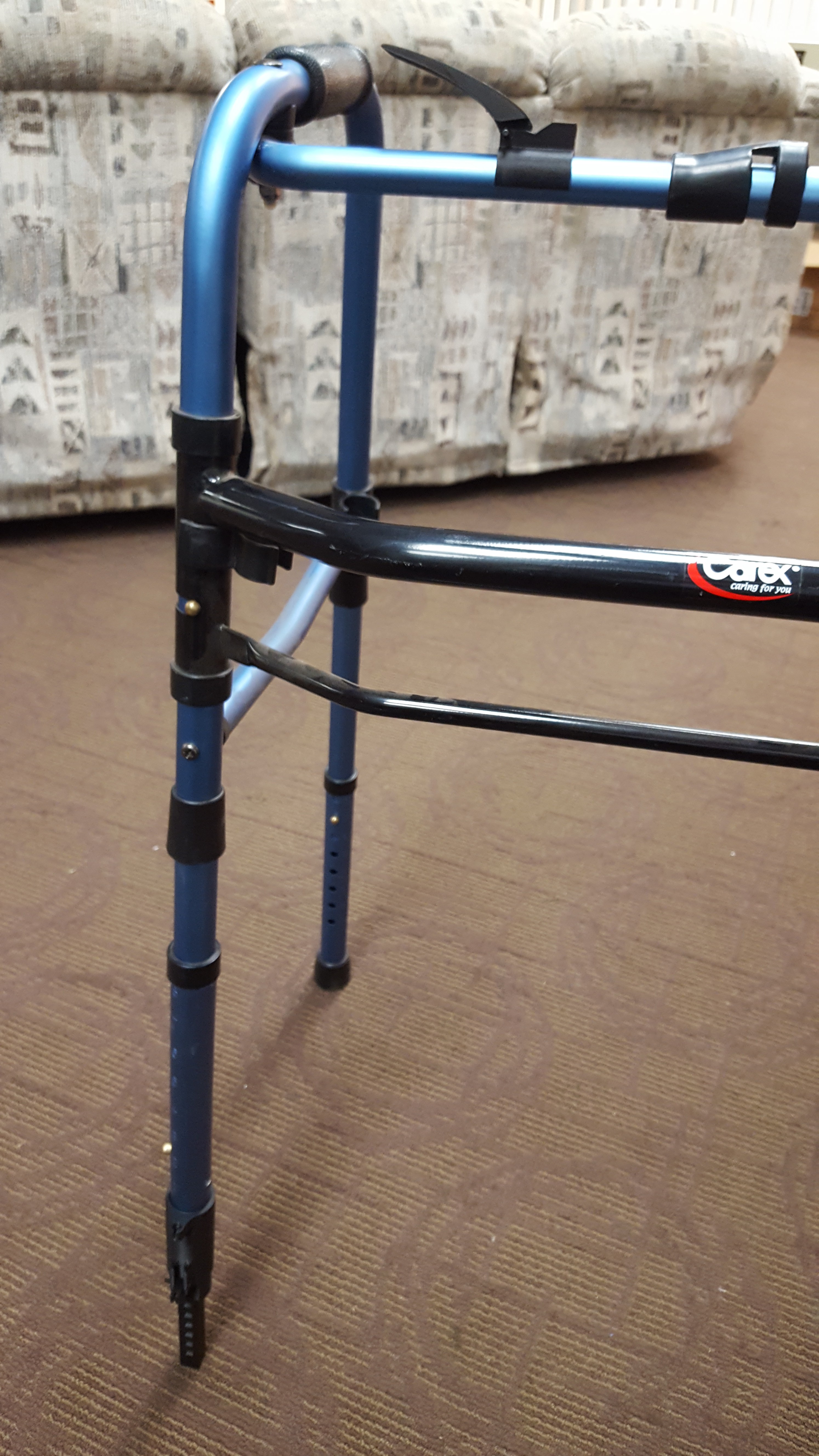
While a standard walker can be a tremendously helpful tool on level ground, it is unusable on stairs. This walker has the ability for the user to extend or retract the front legs to adapt to the current stair geometry. Once the front legs are extended or retracted to match the current stair, it has the stability of a walker so that the user can safely and comfortably go up or down these stairs. When the user is back on level ground, the device will resume its normal configuration and function as a standard walker.

This tool provides the elderly or disabled with the ability to continue to live in both a home with stairs and a world of stairs as well as they now do on level ground.

We have an 89 year old Aunt who has lived in the same house for over 50 years. She absolutely loves this house and does not want to leave. However, the house has many stairs making it difficult to get around. She is afraid that she will have to move because of her limited mobility in her own home. Helping her age in place is the motivation behind the Staircane concept.

A walker is an invaluable assistive device providing mobility on level ground.
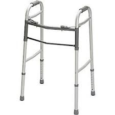
A set of stairs, however, presents an insurmountable problem. The walker was not designed for stairs,  and is unuseable on stairs.

The Staircane is an extension of the standard walker design. On level ground its operation is identical to a walker. However, when the user comes upon a stairway, the user activates a hand trigger  to reconfigure the the front legs to match the stair.

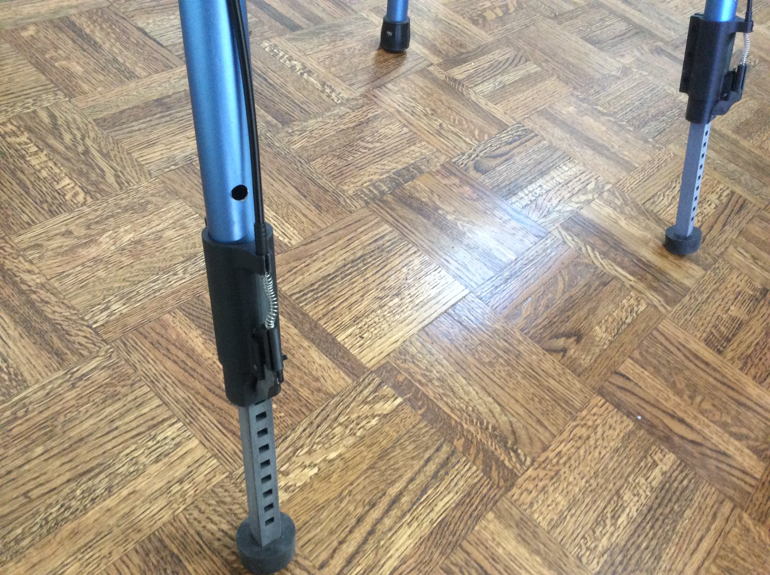
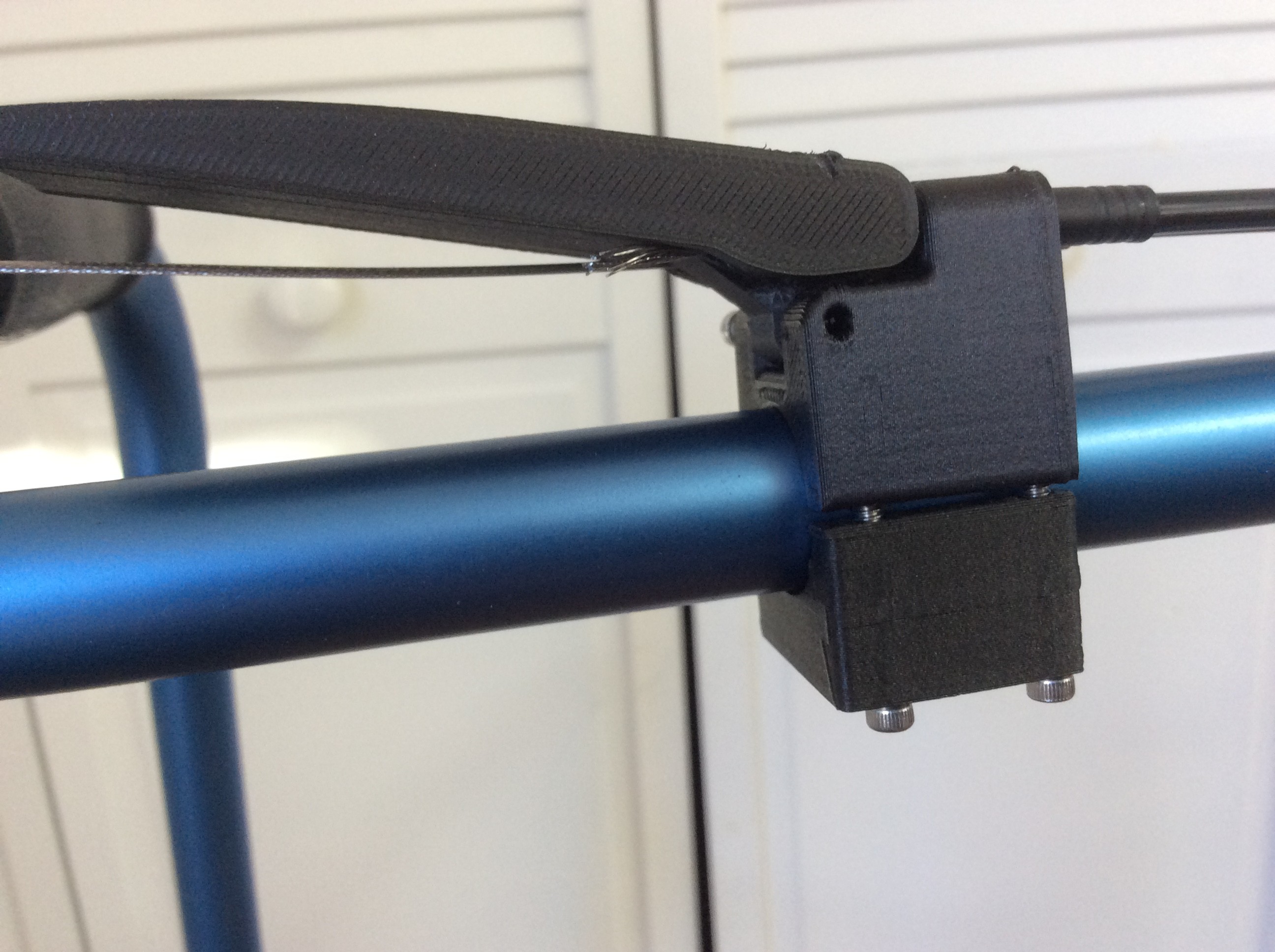
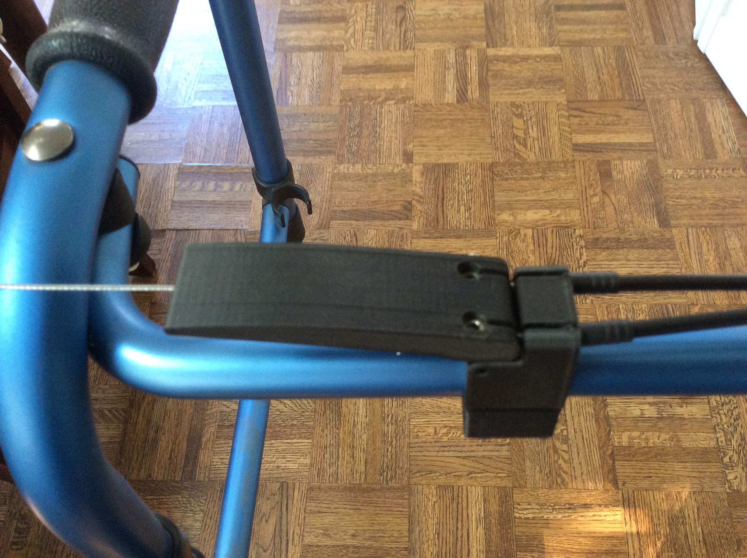
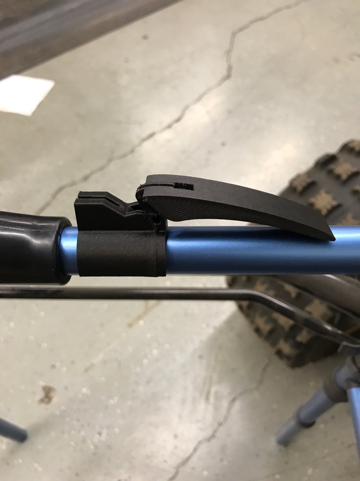
A trigger mechanism extends or retracts the front legs to match the current stair size. When the trigger is activated, the attached cable pulls up on the release trigger.
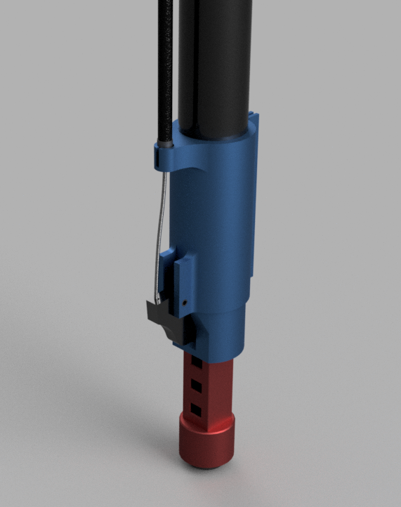
Releasing the trigger allows the front legs to extend or retract to the current stair size. Once the walker configuration matches the stair or level ground, the user releases the button, and the trigger locks back into the extension. Thus, making it usable for going up or down stairs or returning to level ground safely.

Two plans for eventual roll out of the Staircane are under consideration. The first plan would be to develop the adapter bracket that is shown above to be retro-fitted onto existing walkers. It will be sold as a conversion kit. The walker market will have to be studied to see how many different designs of the retrofit would be required to serve a significant share of the walker market. 

The second approach would be to roll out the Staircane as a single entity. Either  conventional walkers will be procured wholesale or the entire product will be built from purchased (walker parts) and custom (handle and trigger) parts.

The feasibility and utility of the Staircane have been demonstrated, The remaining challenges are field testing the prototype, manufacturing and distribution.

Thanks for reading the Staircane story.

HandleDrawing.pdf

PDF version of handle assembly

Adobe Portable Document Format - 147.75 kB - 10/20/2017 at 18:09

Preview

Staircane Patent Status.docx

Includes information on patent status

document - 13.14 kB - 10/20/2017 at 18:07

Download

StairCane.mp4

Animation of the use and functioning of the staircane on level ground, transition to climbing stairs, climbing stairs, transition back to level ground, walking on level ground, transition to descending stairs, descending, and, finally, transition to level ground again.

MPEG-4 Video - 3.95 MB - 10/16/2017 at 19:16

Download

IMG_0464.JPG

Close up view of hand trigger - Top view

JPEG Image - 1.59 MB - 10/16/2017 at 20:04

Preview

IMG_0468.JPG

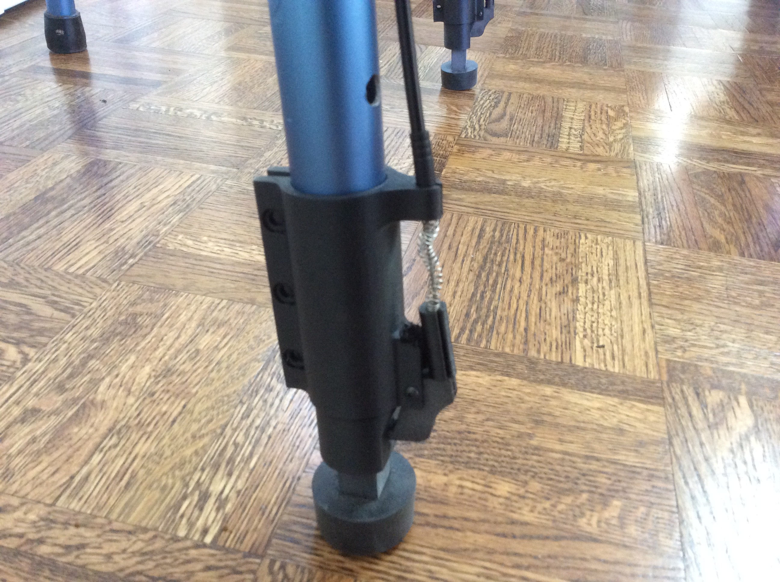
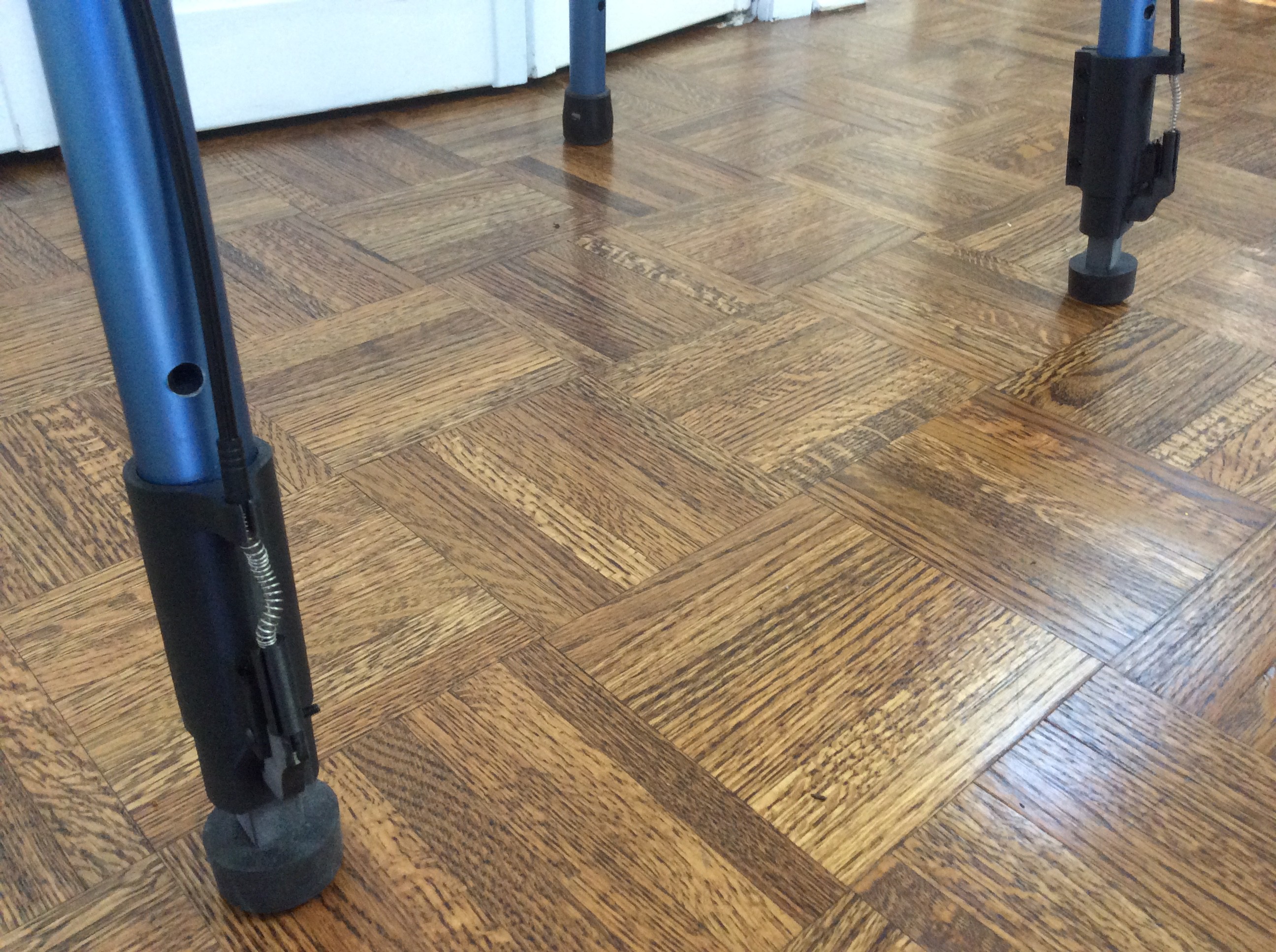
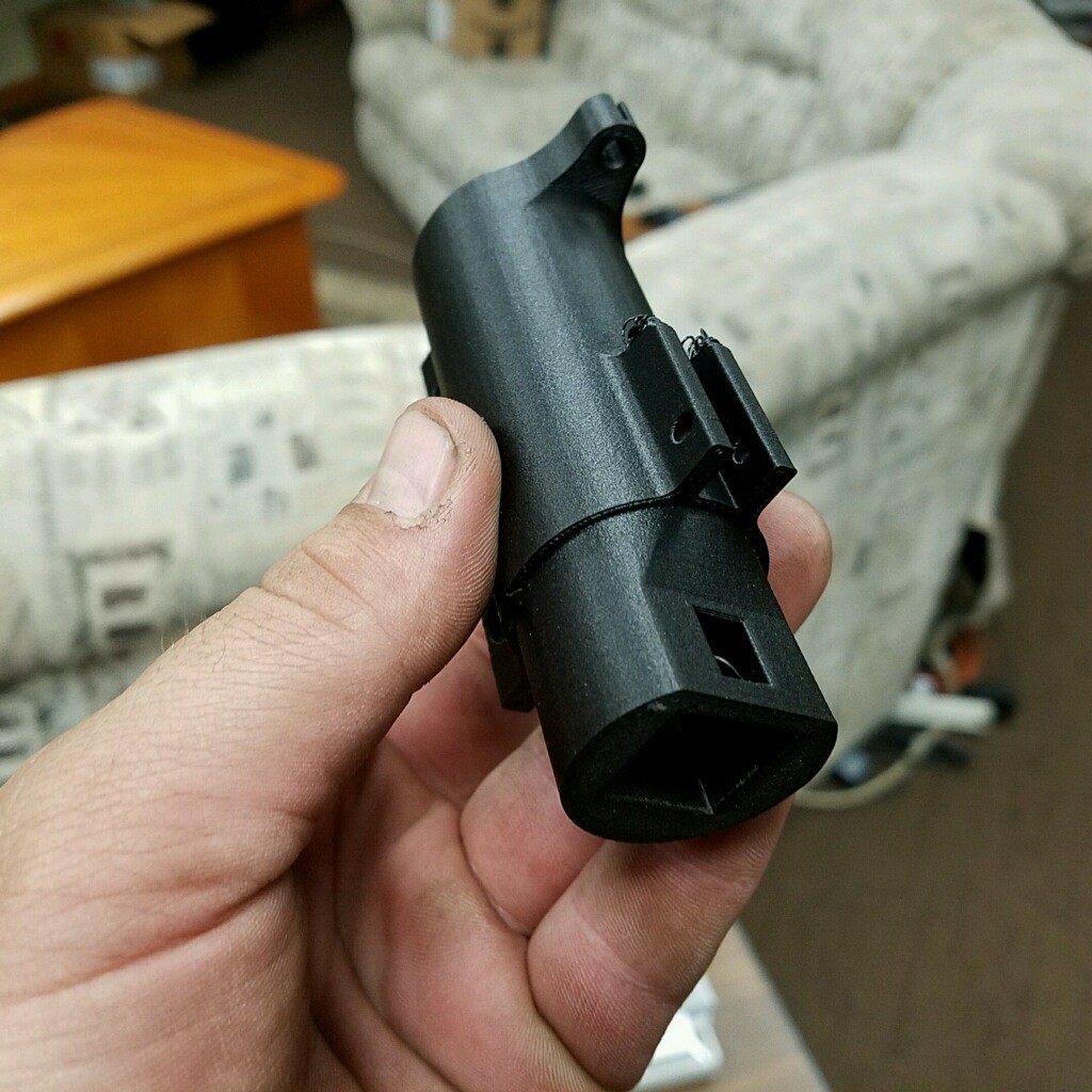
Close up of adapter assembly

JPEG Image - 1.47 MB - 10/16/2017 at 20:04

Preview

View all 16 files

  • 2 × Press Bar (one for front legs, one for back legs) Press this to release the trigger lever (also secures cables)
  • 2 × Press Bar Clamp Snaps onto walker
  • 2 × Labeling Misc. Warning Labels
  • 4 × Spring Placed inside the Adapter to secure lever in home position
  • 2 × Connection Pin Secures Press Bar to Press Bar Clamp

View all 11 components

  • Completed Entry for Finals Submission

    Jim10/20/2017 at 18:14 0 comments

    We finalized all information to present entry in the 2017 Hackaday Prize finals. Updates for final entry include the following:

    1. Include file on Patent status
    2. Include drawing file of handle assembly
    3. Included YouTube videos of a Staircane animation; and of our prototype
    4. Cleaned up some verbiage throughout our project
    5. Recalculate some measurements for extension length

    Good luck to us and our project. 

    Thank you to the Hackaday Team and Judges for their consideration of Staircane

  • Staircane Video

    Jim10/16/2017 at 23:06 0 comments

    This is our 2017 Hackaday Prize video entry.

  • Prototype is Built and Ready for Video

    Jim10/16/2017 at 20:03 0 comments

    The prototype is ready to go

  • Dual Hand Trigger is Completed

    Jim10/16/2017 at 19:58 0 comments

    We completed the dual hand trigger pieces

  • Updated BOM - Component List

    Jim10/11/2017 at 22:51 0 comments

    Updated the BOM list to latest design. I need to get component list nearly completed so that the names are consistent when writing up the build instructions.

  • Hand Trigger Concept

    Jim10/10/2017 at 22:35 0 comments

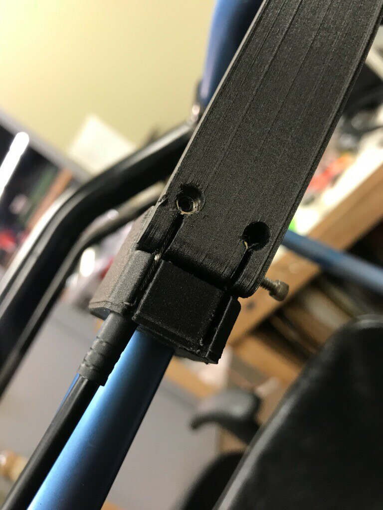
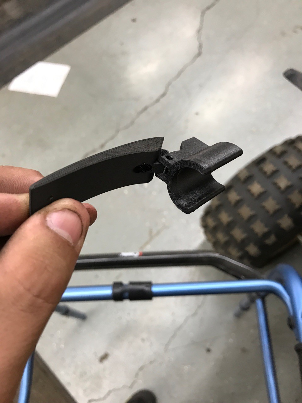
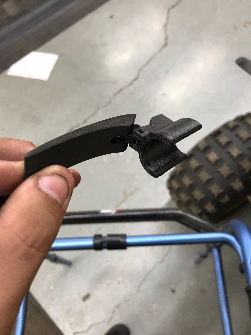
    Created the hand trigger concept. The picture shown below was our beta version which, when depressed, would pull on the cable to release the lower trigger. 

    It was later discussed to have only one hand trigger per set of legs (one set for front, one set for back). This way we'd need only two hand triggers - not 4. This does not show the dual concept as this was just a beta. 

    Hope we can get the dual trigger shown tomorrow. 

  • Parts Made on the 3D Printer

    Jim09/27/2017 at 22:22 0 comments

    9/19: The 3D printer is now live and activated. 

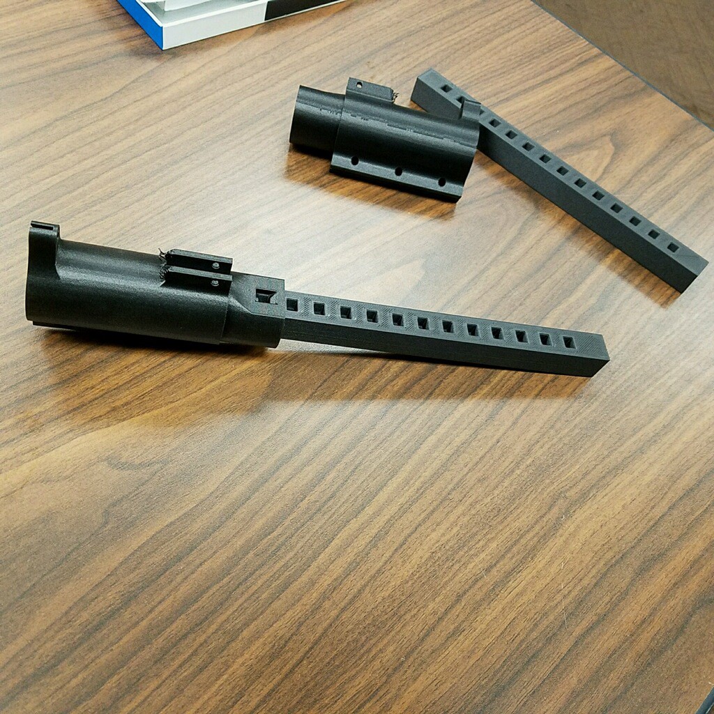
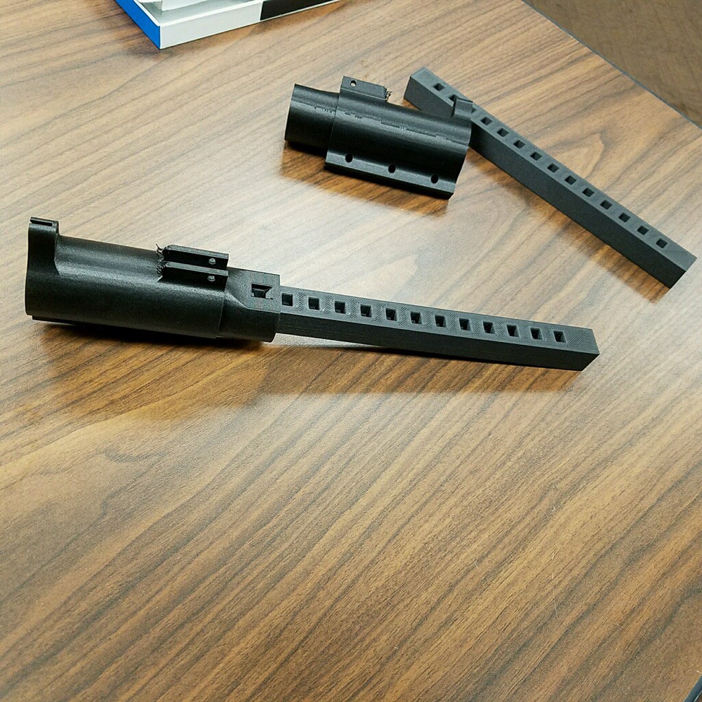
    The bottom mechanism was loaded and then build via the newly acquired 3D printer to see if it could make the parts for the prototype. The adapter, the extender, and the locking mechanism were made. Having success with this allows us to make modifications much easier. 

  • Review Steps for Finals Submission

    Jim08/18/2017 at 15:32 0 comments

    Celebrated the fact that we made it to the finals!! Thank you Hackaday voters!!!!

    1. We'll make the hand trigger mechanism prototype
    2. We talked about ensuring that the trigger is engaged into the extender
    3. We need AutoCAD drawings updated and available to team members
    4. We'll submit video with triggers for only front legs (for going down stairs)
    5. Discussed provisional patent with team

  • Upcoming Milestones

    Jim07/06/2017 at 23:48 0 comments

    2nd Quarter 2017

    • Submit Hackaday project

    3rd Quarter 2017

    • Complete handle prototype
    • Test linkage between handle and activation lever

    4th Quarter 2017

    • Define/refine BOM
    • Test Materials
    • Retrofit model

    1st Quarter 2018

    • Fabricate final prototypes
    • Self-Test Model

    2nd Quarter 2018

    • Refine BOM and price materials
    • Retrofit walkers
    • Live subject testing

    3rd Quarter 2018

    • Our Aunt can stay in her house

  • Testing

    Jim06/23/2017 at 15:55 0 comments

    September 2016 Static prototypes for up and down configurations built and tested for stability

    October 2016 User testing of static prototypes confirmed stability and useablility

View all 12 project logs

  • 1
    Step 1: Making 3D Parts

    Several of the components are now made on a 3D printer (Press Bar, Press Bar Clamp, Release Trigger Lever, Adapter, and extender). There will be a point in manufacturing that this is no longer feasible, but for prototyping it works well. These components are designed and tested using this process

    Press Bar and Press Bar ClampPress Bar and Press Bar ClampAdapter and ExtenderAdapter and Extender 
  • 2
    Step 2: Procuring Purchased Components

    Several components are going to be purchased (springs, connection pins, foot, and cables). These are standard components that for prototyping and various design samples are not required to be custom made.

  • 3
    Step 3: Mate Components

    There will be mating of components required at the "factory" level. This includes pinning the Press Bar to the Press Bar Clamp (x2), pinning the Release Trigger Lever to the Adapter, installing the Spring to the Adapter, and screwing the Foot to the Extender. 

    There may also be some pre-cabling that could be done so that the customer is not required to do this. The pre-cabling will be decided at some later date is it may not be feasible to be done at the factory level. 

View all 5 instructions

Enjoy this project?

Share

Discussions

Jim wrote 05/09/2017 at 01:14 point

This project is still under development, but welcome any and all constructive feedback. 

  Are you sure? yes | no

Similar Projects

Does this project spark your interest?

Become a member to follow this project and never miss any updates