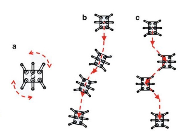
Figure 5.1 Omni-directional Locomotion Types, adapted from [2]
Figure 5.1 shows the 3 omnidirectional locomotion types that can be implemented in hexapod robots to change direction while navigating within an environment. MapleSim simulation environment was used for developing robot models for each omnidirectional locomotion type and for testing the hierarchical control architecture that has been presented in Chapter 4.
5.1.Centroid Rotation
Figure 5.1-a shows a hexapod robot rotating about its centre, such manoeuvrability provides a great advantage to legged robots when changing direction within a limited movement area [2]. Figure 5.2 shows the simulation results that have been generated by implementing the centroid rotation. It can be seen that hexapod robot is capable of rotating both clockwise and anticlockwise directions and it is possible to alter the step size in order to speed up the process. Notice that in Figure 5.2, the step size of the bottom hexapod is greater than the top robot.

Figure 5.2 MapleSim implementation of centroid rotation.
The 3 videos below show the MapleSim simulation results.
5.2.Slalom
Figure 5.1-b shows the slalom movement capability of the hexapod robots. The robot plans its motion as a combination of centroid rotation and straight walking. It divides its body path into linear lines and rotates about its centre between each linear line segment to align itself with the next linear region.
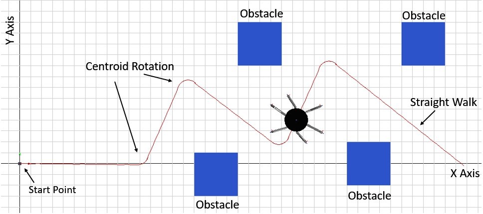
Figure 5.3 MapleSim implementation of slalom locomotion.
Figure 5.3 shows the slalom implementation in the MapleSim environment where the red line shows the path trace that the robot has followed. The code that was used to deduce the direction of rotation is provided in Figure 8.4 (in Appendix).
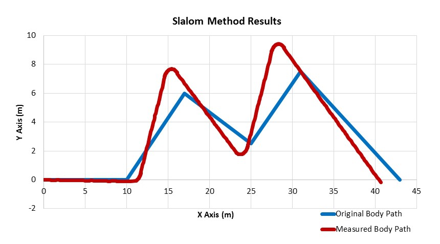
It is seen from the graph below that the robot is slightly off from the given path which is mainly a timer issue. The robot rotates about itself for 30 seconds which corresponds to about 45 degrees of rotation. This could be altered to ensure that robot follows a closer path to the blue path. However, once the dimensions of the robot is considered the robot is not that far off from the desired path.
5.3.Pedestrian-lane-change
Figure 5.1-c shows that the robot leg is moved diagonally depending on the direction of motion and the body maintains its initial orientation at all times. This particular locomotion type is named as pedestrian-lane-change by [2] and the results obtained from the MapleSim implementation are provided in Figures 5.4-5.6.
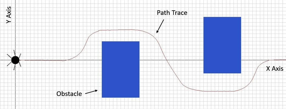
Figure 5.4 Top view of the pedestrian-lane-change locomotion.
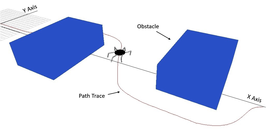
Figure 5.5 3D view of the pedestrian-lane-change locomotion.
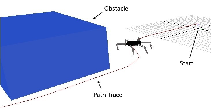
Figure 5.6 3D view of the pedestrian-lane-change locomotion.

Figure 5.7 The comparison of the variation in Y axis against time.
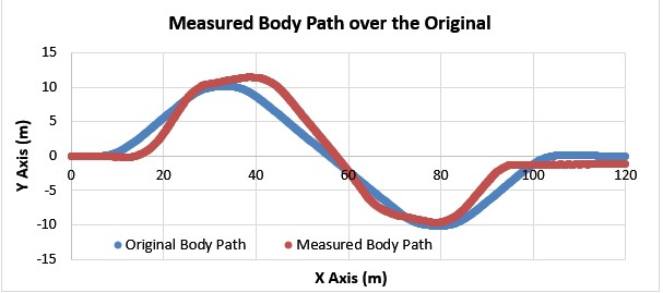
Figure 5.8 The comparison of the variation in Y axis against X axis.
Figures 5.7 and 5.8 show that the body path that the robot has followed. Considering that the wingspan of the robot is about 6 meters, the measured body path of the robot, shown in red, is almost the same as the actual body path that was calculated by body path planner, shown in blue.
PRM Path Planning Implementation for Obstacle Avoidance
- Probabilistic Roadmap Method (PRM) is used to obtain a set of positions that are located on the obstacle free trajectory.
- The quintic polynomial trajectory generator uses these intermediate positions to generate the foot trajectory.
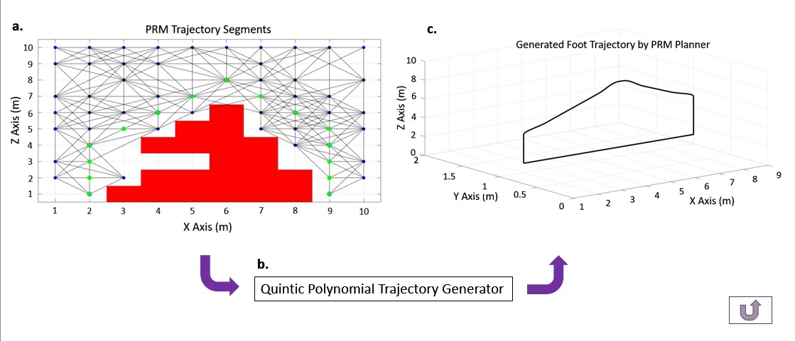
The simulation recording shows how this method works in action...
Discussions
Become a Hackaday.io Member
Create an account to leave a comment. Already have an account? Log In.