 Hexastorm
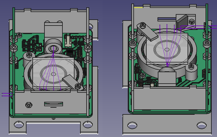
Changes:
decreased thickness PCB from 1.6 to 0.6 mm
mirror is placed back into the design (see my blog on optical weakness)
increased Bugeja coil size, track length coil increased to 287 mm from 144 mm
changed pinout (adapter board should no longer be needed)
diode voltage over all motor pins can be measured
resistor can be used to scale down motor driver voltage
Expected Results
Track length coil increased with factor 1.993
Radius where poles are placed on increased from 8.25 to 11.25 with factor 1.36. (torque is radius * force)
PCB thickness decreased to 0.6 mm from 1.6, square law implies factor 7.
If it is assumed the board can loose 1.7 Joules via convection**, current is expected to be 0.24 Amperes.
Current decreased by 0.75
Motor should be (1.993*1.36*7*0.75) = 14 times stronger
Research Focus
I have been able to show that the prism can be spun and speed looks sufficient.
Current aims are
- achieve facet overlay with 3D printed encasing
- test rotational stability
Lead time
I expect to have some results at the end of July.
**
I measured the board reached a temperature of 60 degrees with 0.32 Amperes at 5 Volt.
Discussions
Become a Hackaday.io Member
Create an account to leave a comment. Already have an account? Log In.
I don't fully understand how your motor is designed but making it as wide as possible seems like it should help with stability.
Are you sure? yes | no
Glad to see you are progressing nicely. I would like to remind you of common assumptions that may impact your work.
* "PCBs are flat": every trace is a raised surface which will impact aerodynamics.
* "the PCB matches the CAD file": micrometer deviations are the norm and will impact the flow of electrons on your PCB coils.
* "magnets are uniform": field strength and shape vary from each and every magnet and their positioning is never perfect.
* "the motor driver is putting out a sine wave": it approximates one (badly), so you may eventually want to build your own driver.
I wouldn't worry about the PCB being flat until you move to a non-3d printed spinning surface. However, if you aren't doing it already then compensating for defects using software would be prudent.
Here are some papers that could be helpful in compensating for these defects:
DOI:10.1177/0278364915599045 with additional material: https://www.modlabupenn.org/anticogging/ (correction via modeling)
DOI:10.3906/elk-1406-54 (correction via neural network)
http://www.komel.katowice.pl/ZRODLA/FULL/102/ref_46.pdf (math for calculating torque ripple)
Are you sure? yes | no
Gravis, thank you for the references. Indeed, there are a lot of challenges with the pcb motor. I do have some degrees of freedom. The prism does not need to remain in the center during rotation. It should just remain in the same plane. I could combine the information of the Hall sensors with that of the diode to improve the way the position is determined. Let's see where challenges arise.
Are you sure? yes | no