 Hexastorm
The Firestarter PCB was designed in Altium. For the new design, I plan to use Kicad, for progress see Github.
It will consist out of two boards; a main board on the Beaglebone with three stepper drivers and a control board to drive the laser diode and measure the photodiode voltage.
In the original design, I used a voltage divider to measure the photodiode voltage. The resistor was chosen with the Axel benz formula. A resistance of 340 kOhm works.
However, a photodiode is something different than a photoresistor. Electronic designer recommended to use the "proven" method. Use an op-amp to read out the voltage. Subsequently, use a Schmitt trigger to get a block pulse. This was also used by H zeller in Ldgraphy.
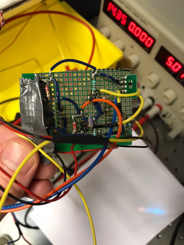
I build the circuit and got it to work with 220 picofarad for C1, see circuit.
The signal is still sensitive to stray light, so use a cap around the photodiode. The photodiode must be placed closely to the rotating prism to fetch all facets.
Circuit:
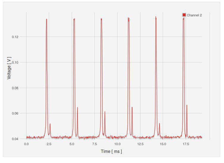
 Signal at TP5/ vphoto in design.
 Signal at hsync in design.
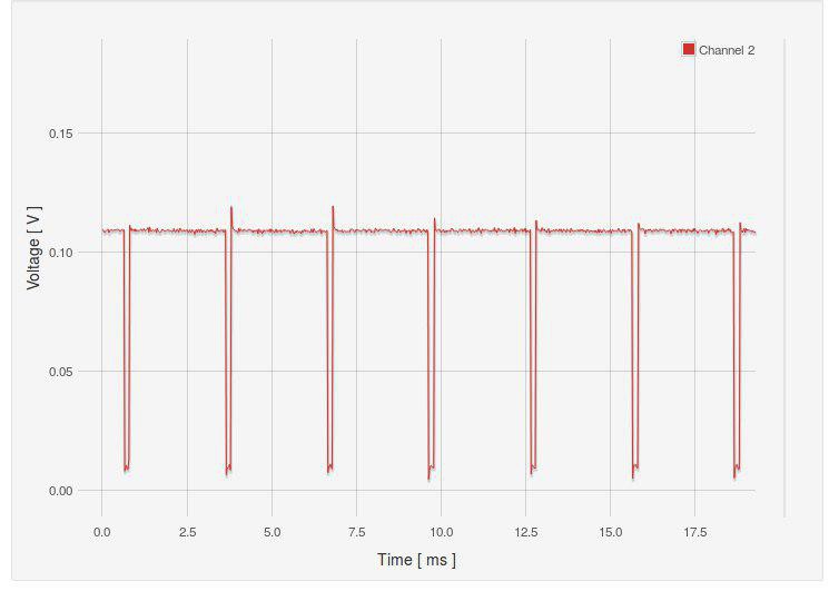
Discussions
Become a Hackaday.io Member
Create an account to leave a comment. Already have an account? Log In.