 Hexastorm
The process goes from right to left. First the clamping pin is removed so the mirror can be released.
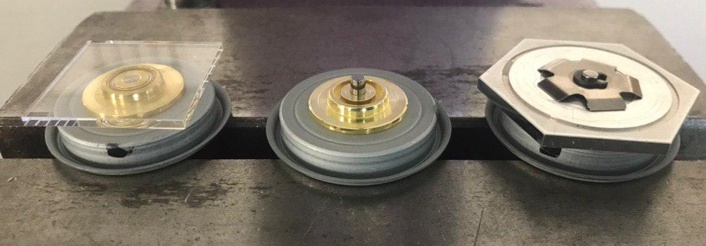
After removing the clamping pin, I removed part of the metal central axis so the first ring can act as reference substrate. I used a spinning mill, a DIY alternative is a hand drill like a Dremel.
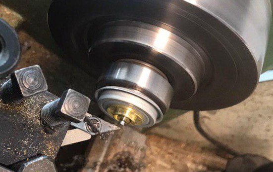
A TESA hite 700 is used to assure that the cut is deep enough, and the inner ring ring is lower than the outer ring. A DIY alternative would be to use a micrometer gauge.
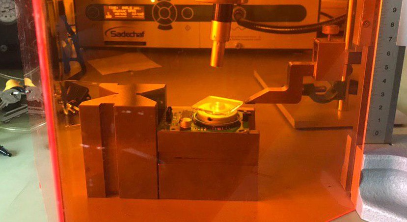
The polygon base is then placed back on the motor. UVacryl 2295 is deposited on the center ring and the prism is placed on top of it. This can be done by gloves or a pen-vac. The distance with respect to a reference pin is measured while the prism is rotated. This assures the prism is centered.
UV light is used to fix the prism in position. I used the blue point 2 from easy cure for 120 seconds. An UV led light at 375 nm suffices as well.
In physics, it is easy to show that being reflective or a mirror has disadvantages. A mirror is four times more sensitive to the facet to datum error than a prism. The facet to datum error is key as it results in the cross scan error which is hard to remove. Jitter can be removed via the photo diode.
If a mirror has a facet to datum error of one degree, the total error is two degrees. If a prism with a refractive index of 1.5 has a facet to datum error of 1 degree, the total error is 0.5 degrees, see deviation angle prism on Wikipedia.
Discussions
Become a Hackaday.io Member
Create an account to leave a comment. Already have an account? Log In.