 Hexastorm
One of the challenges still open is how to balance the prism. Earlier, I discussed the mechanics in a blog named prism balancing. In this blog, I want to give a practical example of how to determine the mass and position from measurements.
Vibrations caused by a spinning rotor are measured with an accelerometer. As sensor, I used the MMA8452Q but would recommend the MMA8451Q or LIS3DH as they have better specs. I used the Raspberry Pi 3B to measure the signal and generated a signal for the polygon motor via hardware pwm using pigpiod.
I pulsed the rotor at 20 Hertz and recorded the vibrations for 1 second at 800 Hertz sampling frequency.
Sampling of the signal must be equidistant or otherwise the discrete Fourier transform can not be calculated. As mirror motor, I used the Panasonic AN4000A.
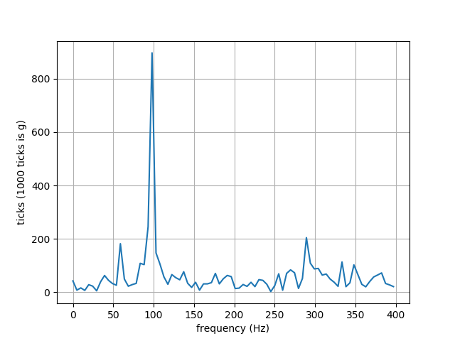
The discrete Fourier transform of a balanced mirror, shipped with the motor, is shown below
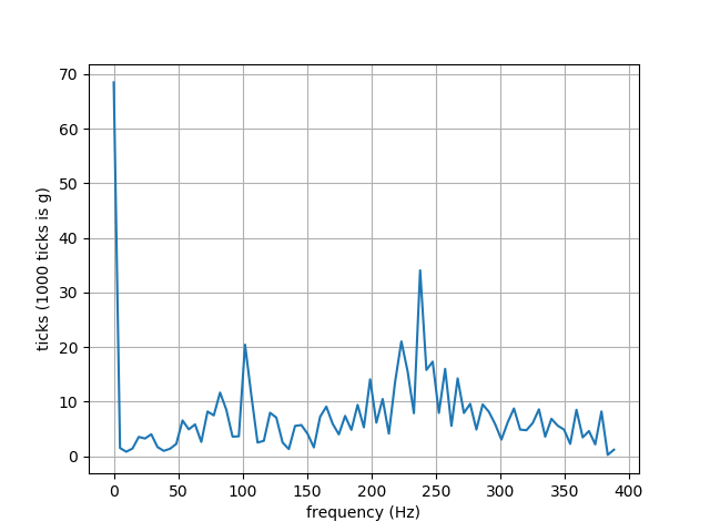
There is a peak around 100 Hertz. The discrete Fourier transform of one of the prism I use is shown below.
An enormous peak close to 100 Hertz can be seen. This amplitude can be compared to the amplitude of a known balance weight to determine the required mass. As the centripetal force is linear proportional to mass. This procedure is only so simple for single plane balancing, in two plane balancing the procedure is more complicated.
To determine the position of the mass, the position of the rotor must be measured. For example by using a photo tachometer. Earlier, I discussed how a camera can be used to measure the position of the rotor. A camera is quite expensive and it would require some image analysis.
The DT2234C+ photo tachometer only costs 18 dollars. It was also discussed widely on Hackaday.
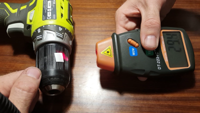
As a result, I bought one and did a couple of experiments with it and attached reflective tape to one of the corners of the prism. The photo tachometer measured a speed of 5750 rpm, i.e. 96 Hertz.
This corresponds to my measurements as I can see a peak near 100 Hertz.
This also explains why I have so many problems with this motor and recommend the Sharp 160.
The Sharp 160 is able to spin at 2000 RPM. Also the relation between pulse frequency to the motor and the final RPM is direct. Pulsed at 20 Hertz the Sharp would spin at 1200 RPM and not 5750 RPM.
The position of the peak in the cross-correlation of the accelerometer and photo tachometer will be an estimate of the phase difference.
If I know the phase-difference with respect to the marking used by the photo-tachometer, I can use that to calculate the position of the balance weight.
The code used for the measurements can be found on Github. I also did a successful experiment with an artificial signal to calculate the cross correlation.
I still have to extract the signal from the photo tachometer and turn on the photo tachometer digitally instead of with a button. Also, I have to order balance weight. Ben Wishoshavich pointed out I could use armature balance putty.
Discussions
Become a Hackaday.io Member
Create an account to leave a comment. Already have an account? Log In.