 Hexastorm
I converted Carl Bugeja's boards to Kicad. I used his version 3 motor as starting design. I hope to have results in 3 weeks.
Five motor boards cost around 100 USD, so it could be interesting to try to print these boards with my prism technology.
I did print some boards but still need to optimize my chemical process.
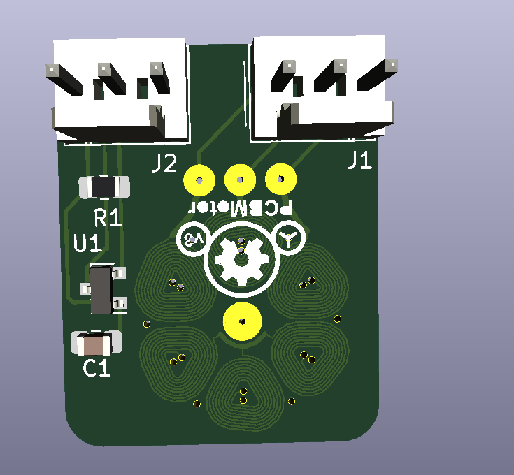
I plan to place the prism on the other side of the motor board, shown below. The motor is driven using the star configuration.
The J1 connector, connects the three phases of this motor. The J2 connector is linked to a hall sensor which measures the magnetic field and can be used to determine RPM.
 I plan to do the control with the FPGA, Carl bugeja used a microcontroller which I removed. The board can connect directly to my FPGA base board. The motor board (shown above) also has a base board, shown below. On it is a brushless motor driver U1). The hallsensor is connected directly to J2 which connects to my FPGA base board (not shown).
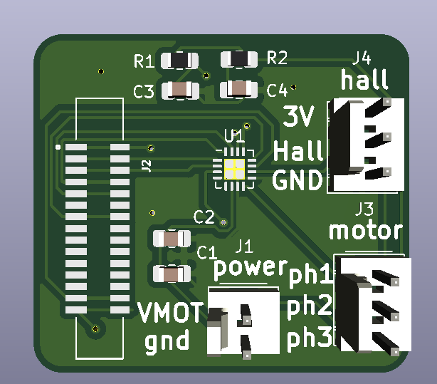 I think chances are high it will work. It would really simplify the design of my product and reduce form factor. Let's see Gravis.. if prisms and pcb motors get a long easy.
Design can be downloaded here https://github.com/hstarmans/firestarter/tree/master/prism-motor/
I will try to add a simulation of the physics, might do some trials with pyleecan.
Discussions
Become a Hackaday.io Member
Create an account to leave a comment. Already have an account? Log In.
This is great though isn't quite what I had envisioned. I was thinking more of putting hole (surrounded by coils) for a large flanged (to ensure it's level with the PCB) bearing in the center of the PCB that would support a lightweight rotating structure containing the prism and magnets. The idea is to use the bearing as a stable mounting platform to avoid lateral wobble.
However, the tightly packed coil design is effective way to reducing the area of the PCB. If you have problems with lateral wobble then you may consider making a mounted structure to suspend a bearing which would act as a stable mounting platform for the prism and magnets. There are many different configurations and materials that should be considered, including configurations where the prism is enclosed in a thin transparent sealed low pressure chamber.
Are you sure? yes | no
correct a flanged bearing would be better.. the design was rejected by pcbway, Carl used advanced manufacturing features I am not willing to pay for. I am making a new one now using a python script.. Will look into the flanged bearings, now used a radial bearing of a racecar
Are you sure? yes | no
I looked into bearings for one of my own endeavors and bookmarked a page to help identify what you can easily buy: https://rhdbearings.com/bearing-size-chart/
That's not the full scope of what you can get but it's a good chunk of it.
I recommend finding out exactly what size and shape you want, try it out with a cheap bearing before buying a high precision bearing (ABEC 7 or 9) from a specialty manufacturer.
Are you sure? yes | no