 Hexastorm
In short; - I am able to increase the speed of the motor using the hall encoders
- prism speed seems sufficient for exposure
- the motor driver dies over time, unknown why
- I will now focus on the mechanical design
In the figure below, you see the commutation states of a motor.
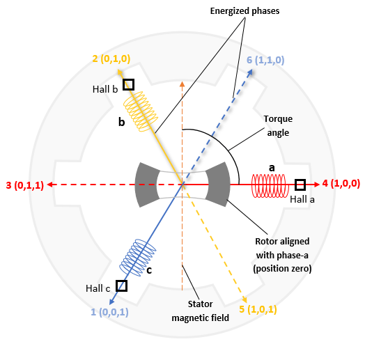 I have three Hall sensors which detect the position of the magnets. There is a total of 8 states,
but the state (1,1,1) and the state (0,0,0) are invalid.
Furthermore the states are ordered, so (1, 1, 0) --> (0, 1, 0) is an allowed transition.
But not (1,1, 0) -->(0, 1, 1) as it skips either (0,1,0) or (0,0,1).
If a state is detected then some coils are turned on and off. The coils also only have six states.
The starting point is random now. That's why in the video, I have to kick it in the beginning.
It's a very crude feedback algorithm but able to spin up the prism. I can also read out the frequency which is detected by the FPGA.
A full cycle is 180 degrees, so the resolution by the Hall sensors is 30 degrees.
The prism ends up in exactly the same position after a turn of 180 degrees. This is not dictated by the quartz but the four magnets below it, which have this symmetry.
The main challenge is that the motor driver, the STSPIN230, dies over time. I start with three working bridges but end up with one working bridge. I have no idea why. I limit the current to the chip below 1A and do not go outside the Voltage range.
An algorithm can also be designed by simulation of the motor, see article. An old implementation in python is provided by open-blcd. This is quite dated. I looked at GYM electric motor. I think it is able to do the same but could not find the time, right examples to set up something fast.
Discussions
Become a Hackaday.io Member
Create an account to leave a comment. Already have an account? Log In.