 Hexastorm
I came up with a strategy to mount the rod onto the prism.
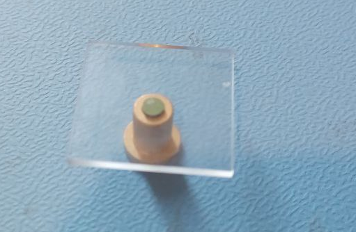
A very viscous putty is placed between the rod and the prism which becomes very hard and green.
The rod hole tolerance is low and the prism rotates over its glass substrate.
You might argue that some of the putty sticks out and this affects the rotation. I cut a small groove in the final version.
Friction seems low,
I will need to check measurements for the cross scan error.
Most interesting would be to compare distorting coming from the prism facets with those coming from the bearing.
In the figure below you see a quartz prism, a sinter bronze sliding bearing and green putty
 In the figure below you see parts separated;
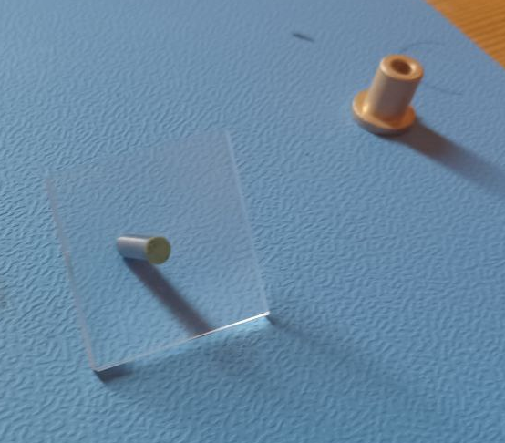 Curing time is around an hour at 50 degrees. The vendor recommends not going over 40 degrees.
Discussions
Become a Hackaday.io Member
Create an account to leave a comment. Already have an account? Log In.
I am mostly skiing this month. I actually made a presentation but to summarize. For a cross scan error of 10 microns you need a maximal deviation of your prism of 4/3 so 13 microns. CNC tuning typically gives you around 30-60 microns of accuracy. This is insufficient. A roller bearing does not work. You r not sure you have a planarity. Aerodynamic might work but is expensive. For lithography the pcbs require a lot light. You cannot go over 3K RPM due to limitations of the laser/resin.
I might have a result by the end of next week. The green putty glue did not work and I have switched back to UV glue.
Are you sure? yes | no
I'm assuming you are still using a regular bearing. Getting a COTS aerodynamic bearing for mounting/balancing (until you have a working design) may help reduce mounting errors.
Are you sure? yes | no