Hexastorm
-
License changes
04/02/2024 at 16:03 • 0 commentsI changed the license of the software and hardware in the project. Code and hardware remain open source but cannot be used commercially unless you have a license. You are also not allowed to make clones.
I am willing to split of parts of the code base under more permissive licenses if this leads to collaboration.Synopsis License Terms (Hexastorm V1)
1. Anyone can copy, modify and distribute this software or hardware.
2. You have to include the license and copyright notice with each and every distribution.
3. You can use this software or hardware privately.
4. You can only use this software or hardware for commercial purposes with a product certified by Hexastorm or paid license.5. If you modify it, you have to indicate changes made to the code unless you purchased the rights not to do so.
6. Any modifications of this code base MUST be distributed with the same license, Hexastorm v1
Modifications not made by Hexastorm cannot be sold unless acquired by Hexastorm.7. This software or hardware is provided without warranty.
8. The author can not be held liable for any damages inflicted by the software or hardware.
9. You cannot charge a fee for a copy or derivative of the software or hardware.Motivation
Licensing the whole project as GPLv3 limits my ability to optimize my legal strategy with relation to other rational agents. I foresee competitive pressure from Asia, given the weak European industrial base and high labor prices.
Furthermore, I foresee increased competitive pressure and interest from the Netherlands. This has been increasing its investment in the sector of laser direct imaging. The Netherlands is strongly against open source.
If you now make changes, I have several options; acquire a license from you, split of part of the work under a more permissive license which allows us to collaborate commercially or write my own code which achieves the same in another way. -
Main board design
02/16/2024 at 10:31 • 0 commentsI envision the development kit consists out of two components; a laser head and a main board.
This post sheds more light on the main board.
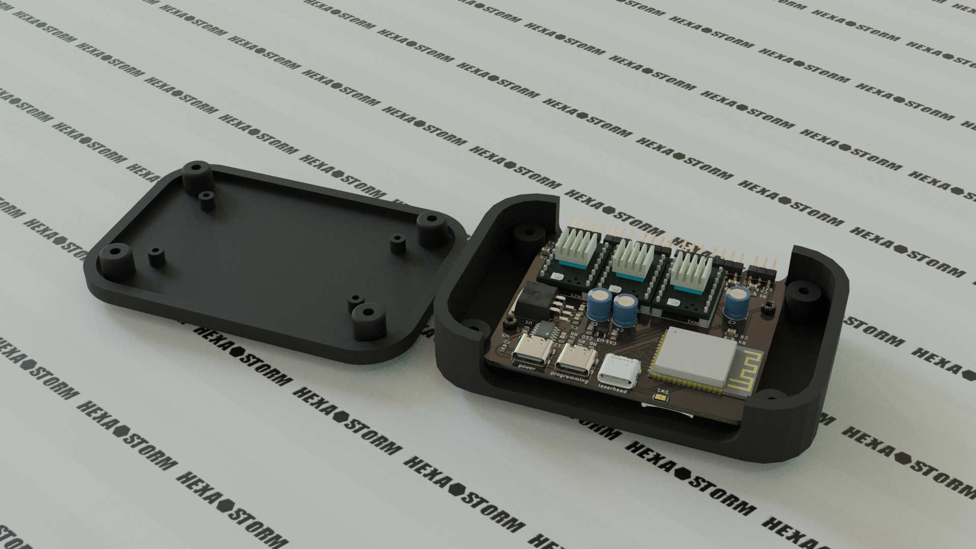
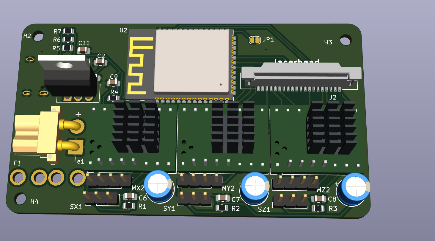
The main board can be programmed and powered via USB C. These are two "regular" USB 2 connectors. The CH224K chip is used to request 12V from the power source. The main board uses a ESP32 S3 and connects to the laser head via USB C 3.1.
This is not a regular USB C connector. In an ideal world, you could connect to the laser head with USB C using your laptop.
I am working towards this, and therefore I am starting to support USB C 3.1. I will share more details on this in the future.
The main board features three stepper drivers, to move the laser head. Angled pin headers are used to connect to the end stops and stepper motors. A micro SD card reader is present for additional storage. The ESP32 S3 already provides 32 MB storage, so this should not be needed. The black box is AK-NW-84 (100x67x22m) and can be found online.![]()
-
Laser Direct Imaging using a PCB motor
01/08/2024 at 15:50 • 2 commentsFinally after all these years a laser direct image using a prism and PCB motor.
PCB motors have come a long way on Hackaday!
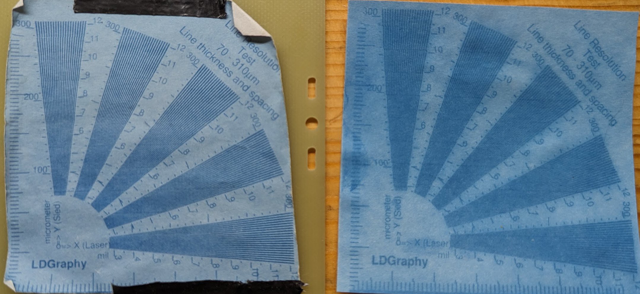
On the left you see an exposure with Ricoh polygon mirror motor and on the right you see the exposure with the PCB motor.
Both use prisms.
The quality of the PCB motor exposure is less, still you can see the concept is working.
I believe this is not due to the quality of the substrate but because I look for the diode between a period fraction of 0.999 and 1.001 for the ricoh motor and between 0.900 and 1.100 for the pcb motor. As such, there is much more back light for the PCB motor. This is explains the blue hue.![]()
@gravis
I ran into a small issue where my stepper motors overheated. As such, I could not expose large areas.
After reducing the current to my stepper motor the setup started working.
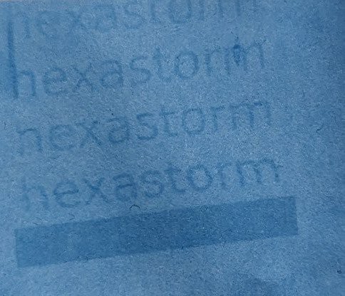
I can now expose larger areas, the area is 65 mm by 65 mm. The area is exposed in 13 sweeps and one sweep is around 10K lines. I do half a step per lane. The material is quite old, had it for years and needs a lot of light.
Possibly the chemistry is not as good as it was. -
A promising start of 2024
01/03/2024 at 15:45 • 2 commentsGood start of 2024; I made the world's first laser direct image using a prism and a PCB motor ...
Lo and behold for the first result !
Video with more details will follow
![]()
-
ESP32 binary to interact with FPGA
11/03/2023 at 16:30 • 0 commentsI am able to make a binary on the ESP32 which can program the FPGA using Fomuflash and initialize the stepper motors via the TMCStepper library.
The controller.py class of Hexastorm can be imported in Micropython. Procedure to make binary is here. -
Update
10/20/2023 at 17:38 • 0 commentsMost people here are probably waiting for an exposure with a PCB motor.
I decided, however, to focus on finalizing the PCBs and porting the software to the ESP32.
I created a main board. The board is built around an ESP32-S3-WROOM-2. I use a USB C connector, but pull 12 volt from a different source.
I removed the micro-SD card, I used in an earlier design. The ESP32-S3-WROOM-2 has 32 MB onboard memory which should suffice. Steps for the stepper motor are generated via the FPGA from the laserhead. The laserhead connector moved from 15 pins to 20 pins.The main board is shown below
The laser head did not really change. I decided to make the screws optional and the plates can be soldered together via pads. I optimized the tracks a bit an moved around some components.
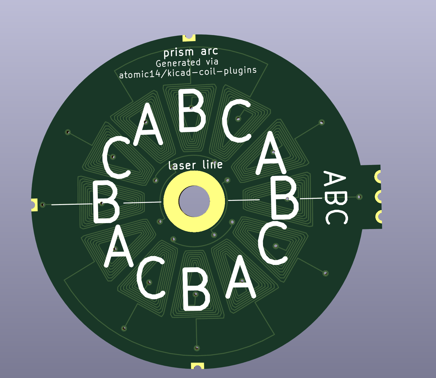
I made a new PCB motor with the code from atomic14. This uses 12 coils and should work better than the archimedean spirals.
There is an even better design on the way. Cooked provided some assistance with the kimotor package see https://github.com/cooked/kimotor/issues/45
I spoke to a couple of mechanical engineers about my sliding bearing. They did not see any issues with the bearing and thought it would be "very" accurate because it was made on a rotary mill.
I aim to do measurement on its flatness at a later stage.
My goal now is to finish the code in Micropython for the ESP32. I hope I can find my earlier prototype which must be somewhere :-). -
when mirrors do not follow law of reflection
09/15/2023 at 10:24 • 1 commentLaser scanning via mirrors is of relevance to prism scanning, being an alternative. For mirrors it is assumed angle in is angle out (law of reflection). Still, this is not always valid. The following article on arxiv goes into depth on the latteral shift and angular shift known as goos hanchen effect and imbert federov effect. It is seems to be simple consequence of Fresnel equations.
Aberration is small but you would have to account for distance to substrate and also compound both effect. Details in article
-
3D printing of ultra-high viscosity resin by a linear scan-based vat photopolymerization system
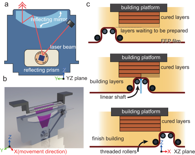
09/07/2023 at 16:33 • 2 commentsLast july, an article was published in Nature for a new high viscosity vat printing method, https://doi.org/10.1038/s41467-023-39913-4
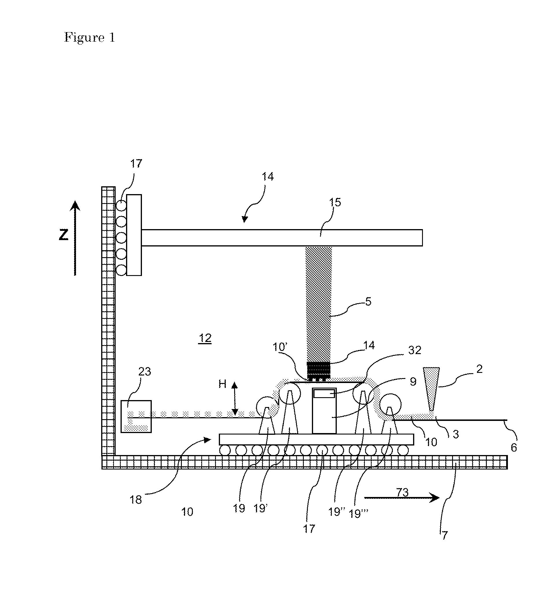
This method is depicted below, the figure is copied from the article.![figure 1]() It uses four rollers to apply a new layer to 3d print a part. The article comes with some cool videos and equations describing the mechanism.
It uses four rollers to apply a new layer to 3d print a part. The article comes with some cool videos and equations describing the mechanism.The method, and this is not mentioned in Nature is not entirely new, see patent EP2272653A1. The only difference i can see from a legal perspective is recoater number 2. I also remember it is not a true vat method. Resin went to a waste box, see number 23. I think the Admatec machine is a spinoff from this concept. It also uses a a rotating foil, coated with a blade and the remainder is put into a left over box.
![]()
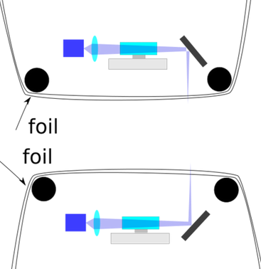
Furthermore, in my white paper on reprap, i claim the usage of a foil with my Prism scanner. I made two drawings to protect up and down projection.
I think the authors of the nature article should consider the following two patents;
US8777602B2 (recoater patent)Loophole might be not using recoater.
US9939633B2 (scanlab, EOS subsidiary patent, reflecting lens)
Their reflecting lens seems very similar to scanlab. The authors mention the 3SP patent, so I did not include it.
-
Flipping a PCB motor using a ferrite sheet
08/30/2023 at 14:04 • 2 commentsI use a sliding bearing. This keeps costs low and ensures the prism is kept in a given plane. A challenge is that the prism falls if this sliding bearing is flipped 180 degrees. This is fixed by adding a ferrite sheet on the back of my PCB.
Materials used flexible ferrite sheet MHLL5040-200 Laird, Magnets MKSA-8x5-ZW-N45 i.e. 8x5 mm, neodium 45 with a black epoxy coating.
I think that ferrite instead of neodium is possible if the whole contraption was made better. Ferrite is typically 2-7 times less strong. If the distance would be decreased a bit, which is still possible, ferrite should work. -
Brief update
08/10/2023 at 16:08 • 0 commentsTwo changes;
- Layout Hexastorm.com changed and is now more in line with look and feel of Hackaday.
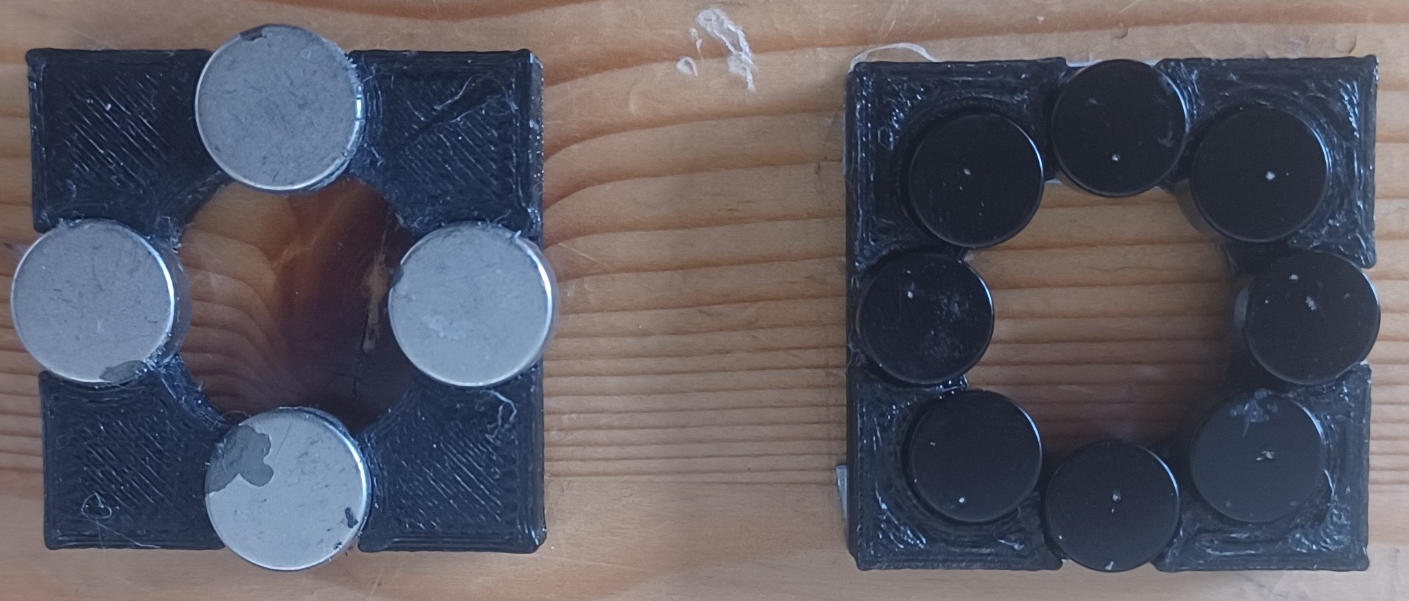
Website is generated using Quarto- Decided to further perfect engine, moved from 4 to 8 magnets. The magnets have a black coating
which aligns better with the overal design Hexastorm.![]()
 It uses four rollers to apply a new layer to 3d print a part. The article comes with some cool videos and equations describing the mechanism.