 Hexastorm
-
pcb windings, mini laser prism scanner and magnetic levitation
02/28/2023 at 21:57 • 2 commentsI got two tips from readers.
Please note that my current focus is construction of the bearing.
Different PCB windings;
The advantages of improving the PCB windings are;
- ability to replace rare earth magnets (neodium) with ferrite magnets
ferrite magnets are 2 or 3 x times less powerful but much cheaper
- it might be possible to go from a four layer PCB back to a 2 layer pcb (reducing costs)
- ability to achieve higher spinning speedsKeith reinolds pointed out that a Faulhaber winding is more efficient than the bugeja coils or the improvement outlined by atomic14.
This is outlined here.
A linkt to a review paper is provided by gravis https://ietresearch.onlinelibrary.wiley.com/doi/full/10.1049/iet-epa.2020.0141Mini laser prism scanner
It could be useful to make a very small laser prism scanner. There are applications in imaging, communication etc. as outlined earlier.
Two things are of interest;
You can buy precise micro prisms, which have dimensions around 1 mm.
https://www.neg.co.jp/en/assets/file/product/ep/micro-prism.pdf
Magnetic levitation
Wikipedia provides a good overview on magnetic leviation.
You might be able rotate the prism if it is made from a diamagnetic material.
Lawrence kincheloe pointed me to an article which does this for a pyrolyte sheet,
https://pubs.acs.org/doi/10.1021/ja310365kI can also imagine you trap a rotating prism with a magnetic trap
-
LASER scanner with PCB motor
02/16/2023 at 11:33 • 1 commentDemo of the first working laser scanner in the world which uses a PCB motor.
It's a simple demo. Nothing is made, only a static pattern is generated. It combines a lot of effort by the community and me :-). Next is building the bearing.
-
simple laser vs laser prism scanner for interlayer bonding
02/15/2023 at 08:42 • 0 commentsGravis, I made a blog for your question.
Your question:
I do ponder the rationale for heating only part of the filament. However, it might be just as easy to use a tiny linear actuator to adjust the laser position than use a rotating lens to change the beam path.
My answer:
If you apply too much heat to the previous layer, the structure could collapse.
Even more heat and it could burn or a reaction will take place.
I guess to keep the structure intact, Stratasys does not expose the edges.
For first experiments I would not even use a linear motor but just make straight tracks and pre-expose them with a fixed laser. A laser with a tiny linear actuator is indeed much easier to make.A laser prism scanner is able to expose the previous layer with a much smaller bundle.
I expect they now use a bundle diameter of 180 micrometers for a nozzle of 300 microns. (0.6*300 microns).I think a laser prism scanner has two advantages;
- if you swap nozzle you don't have to change focus of the LASER.
For a 1 mm wide nozzle your bundle width would have to be 0.6*1 = 600 microns.
A laser scanner would just project a longer line. Stratasys could solve this by
adding a motor to the laser lens.- a laser prism scanner allows you to apply heat much more precisely due to the smaller laser spot.
Using a laser prism scanner you should be able to go well below 60 microns in bundle diameter.
The exposure is more uniform. In the case of a single spot it is a Gaussian. With a laser scanner
you are able to overlay multiple Gaussians, i.e. spots, and achieve a higher uniformity.
I could imagine you need to ensure only the top of the previous layer is heated. If your molecule
chains have a length smaller than a micron, I think 10 microns deep should be sufficient.
It will depend on how heat is absorbed by the structure, the bundle diameter of the laser and
diverging hereafter. The thermal diffusion coefficient and cooling of the structure with respect
to the air / environment.
When the new layer is added you want the large molecules to mix at the edges and not the
structure to collapse.
You could look at the scattered light using OCT / laser microscope to get an idea of the
temperature of the structure and ensure you r not overheating. -
Increased inter-layer bonding with lasers continued
02/08/2023 at 15:21 • 2 commentsThe increased inter-layer bonding using laser scanners has my attention.
Materialise filed for patent in 2015, WO2016049621A1. It abandoned the application.
Siemens, the owners of Hackaday, filed for (WO2018188757A1), where they take into account correction parameters by looking at the previous layer. It seems not directly related.
There are many more HP, Epson US11498266B2 etc.I view patents as the Sport of Kings. Given my experience, I decided to
create prior art. There are downsides, but less costs upfront.Previously, I outlined that the laser line is orthogonal to the direction of the last extruded line.
A possible challenge, is that the laser line does not cover all possible motions of travel.
It should be obvious for a PHOSITA, that with a single line immediately after the extruder your direction of movement is limited to 180 degrees with an orthogonal scan line.I therefore claim the following;
two laser lines are projected to cover both sides, depending upon the motion one would
heat up after extrusion and the other prior. Or one side would heat up both prior and after
extrusion.In additive manufacturing it is often beneficial, to execute the printing process at an elevated temperature via for example a heated build chamber.
This creates problems as lasers and electric motors function better at a low temperature.I therefore claim the following;
the PCB board which forms the basis of the laser prism scanner is placed on top
of a thermoelectric (TEC) cooler. This cools down the side of the laser and the PCB
motor. It heats up the side which is in contact with the heated build chamber.
Earlier, I outlined that a combination of two cylindrical lenses can be used to reduce the cross scan error distortion and create a circular spot.
It might be beneficial to elongate the laser bundle orthogonal to the scan line.
As this increases the area which is heated, whilst still using one laser or led.I therefore claim the following;
a cylindrical lens or other lens is used after the prism which elongates the laser / led bundle
orthogonal to the prism. This is done to increase the area that is exposed by the optical bundle.One could use a plurality of emitters but I doubt that the heating process has to be so accurate.
It should be noted that the quartz prism and lenses can be made of another plastic material i.e. acrylic given its low absorption in the infrared range.
This has the advantage that costs would drop.As such, I claim the following;
The infrared emitter is a light emitting diode, all optical elements for the scanner are manufactured
using acrylics.The control system would need to use data to optimize the heating process.
I imagine that an infrared sensor or camera is present that collects the light emitted from the heated area.
It might be possible to collect this information in the laser scanner using the laser microscope configuration outlined earlier. The information is than used to optimize the image formed by the laser or led scanner. Epson claimed this in US11498266B2, however it outlines that information of a temperature sensor is used for the nozzle heater.As such, I claim the following;
I claim that a temperature sensor is used with the relation outlined by Epson.
but that this is used to control the settings of the lasers and not the nozzle heater as outlined by
Epson.It might be beneficial to use multiple wavelengths. The extruder could extrude a thermoplastric material in combination with a resin. In these cases, it might be beneficial to combine the infrared laser with a UV laser.
-
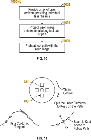
Laser preheating in three-dimensional printing
02/07/2023 at 08:27 • 1 commentThe aim is to construct prior art to circumvent US11192298B2 (Stratasys)
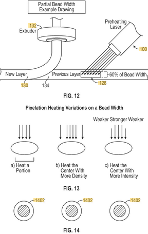
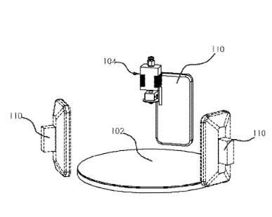
Stratasys envisions the preheating process as follows
![]()
The projection is along the filament line and less wide than the beam width.
The laser is kept on the filament using theta control.![]()
Stratasys seems to think it it necessary / optimal that the laser image has a width less than a commanded bead width of the bead.
I propose the following a laser prism scanner projects a line orthogonal to the filament path.
This circumvents the patent as the projection is greater than 50-75 percent of the bead width.
It also no longer requires theta control. Only the part of the scanline is used which optimally preheats the filament is required. Intensity could be altered over the filament.It might be beneficial to extend the prism and use a plurality of emitters (lasers or leds). As it allows for a more careful preheating of the filament.
This would then bring us into the legal domain of US10114289B2 and the activities of my former colleagues (AMsystems).
You are using a plurality of emitters through a rotating prism.As alternative a combination of two rotating prism could be used with a single laser.
A stack of laser laser prism scanners could be used. That is multiple laser prisms scanners are placed in front of the extrusion. This could be beneficial if the distance required is sufficiently large.
That it is more cost effective than a single prism with a plurality of radiative sources.As outlined earlier, I claim all the above for the case this is done after the extrusion.
This is possible beneficial as well. -
Thermal Radiation Heating Patent Loophole
02/06/2023 at 08:50 • 0 commentsI studied the thermal radiation heating patent US20210387401A1, a bit more.
Orion AM basically claims it solved the homogeneity issue for fused filament printing, see picture.
This is big. At first sight, there seems to be an issue with their patent.
If you look at the actions from the US patent office, you see that the first 11 claims are withdrawn and the 12th claim is amended.
It has one big loophole; " at least one print heating device for applying thermal radiation"
Thermal radiation is electromagnetic radiation generated by the thermal motion of particles in matter.
Solid state lasers and LEDS do not create electromagnetic light via thermal motion.
As such, you are able to circumvent it.
Reason seems to be that using lasers to increase bonding between layers has been patented by Mark Gordon in 2016 US9339972B2.The patent expired due to fee issues. Someone seems to have made an expensive mistake here.
There seems to be some other patents, one which also uses a roller.
A crucial one is by Stratasys (https://patents.google.com/patent/US9339972B2/en)![]()
Key seems to be that they apply the laser prior to deposition. Stratasys seems to envision some sort of of theta control.
-
Thermal Radiation Heating using laser scanning
02/01/2023 at 10:12 • 0 commentsFused Filament Fabrication (FFF) suffers from weak interlayer bonding, delamination and warping because the material cools down after being deposited.
Orion AM uses thermal radiation, the heat penetrates through the material, allowing the layers to truly fuse together. This results in parts that are more uniform in strength, more dense and stronger.
With pictures, Orion AM shows it is able to increase the strength in the z-direction 10 times (https://www.orion-am.com/thermal-radiation-heating) .
I am not surprised it is possible, but impressed by the proof they gave.
Adam Rumjahn filed a patent US20210387401A1. The first 11 claims have been withdrawn.
Adam outlines it is key to match the spectrum of the IR source with the absorbance spectrum of the filament. I can imagine that a lot of heat is absorbed at the interface between the layers.The following figure is from the patent.
![]()
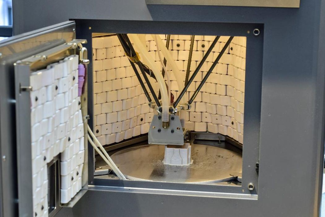
In reality this looks a follows;
![]()
I think laser scanning or a laser could add a lot of value here. I want to claim the following and add to the public domain.
The material would be deposited with fused filament fabrication. After deposition, a laser scanner would use IR or UV radiation to perfect the bonding between the layers. The laser scanner could use optical coherence tomography or simply look at the scattered light to monitor the bonding process. Key seems to be that the heat penetrates through the part and heats up the interface.
An alternative would be to apply the laser radiation prior to fused filament or liquid deposition.
I can imagine that using a laser to heat up the previous layer before a layer is placed on top of it could also work. This might simplify things as it does not needs to penetrate through the previous
layer.
In a preferred embodiment, the laser head is integrated with the fused filament deposition head.
I assume that the laser heating process is much faster than the deposition.
Naturally, the whole process takes place in a heated build chamber. The advantage of using a laser scanner would be that you can more precisely apply and monitor the addition of IR or UV radiation. You could better control the fusing process.
Besides the applications outlined by Orion AM a very good application could be glass printing.
Delamination is a big issue here as it make the resulting glass structure not uniform. This is very apparent. So here heating the previous layer with a power full laser before extrusion of the glass, might also fix the de-lamination issue. -
PID controller in Amaranth HDL / FPGA
01/31/2023 at 11:57 • 2 commentsI finished the PI controller. Speed seems very stable like 1998-2002 RPM when the target is 2000 RPM. Next step is to restructure the code base and add laser measurments.
-
Plan for an improved BLDC controller
01/05/2023 at 10:32 • 4 commentsRotating polygon laser scanners need to keep track of the angular position of the
prism or mirror.
In an earlier version of Hexastorm, this was achieved with a Sharp A160 polygon
motor. This board has a NIBC3111 chip. Motor speed could be
controlled by sending a PWM signal to this chip.
Using Hall sensors,
the internal circuitry of the board was able to stabilize the rotor
speed.
I added, a photo-diode and FPGA to accurately track the prism position.The current approach has several limitations;
- the control algorithm is not open-source and hard to port to the PCB motor
- the performance improvement by the photo-diode is not known,
the design would be much more compact without photo-diode and just hall sensorsAs a result, I decided to develop a new control algorithm. Let's say I want the energy to be uniform within 10 percent. This implies the angular velocity must be constrained within a Mean Average Percentage Error (MAPE) of ten percent. I need to know the angular position of the rotor within a MAPE of 0.005 percent. If it is assumed the line length is 24 mm, and the angular speed is uniform (in reality it is not but close), the exposure accuracy is 24*(0.005/100)=1.2 microns. In my experiments so far, I used a speed of 2000-3000 RPM.
My experimental setup has several constraints. I don’t uses a micro-controller, so I try to avoid divisions and multiplications in my control algorithm. The hall sensors produce six states but these are not evenly spaced. I already have a controller in place, which was implemented in 2022.
The current controller first speeds up the rotor by flipping to the next state after a given time.
This ensures the rotor is rotating. Once rotation is established, the controller switches to hall feedback mode. It simply enables the “right” coils given the currently measured hall state.
Speed can be measured by counting the time it takes to transition between 12 Hall states (i.e. 360 degrees).The critical path is seen as follows;
1. Measure the speed of the rotor
There are 2x6 states in one rotation. If the new hall sensor state is not equal to the old hall sensor state. The old hall sensor state is updated AND one count is added to the number of states seen. If the total is six, the counter is reset and its value represent the time for six states.
If the hall sensors are sampled at a "too high" frequency this results in a lot of noise.
It turned out to be key to divide the clock frequency from 12 MHz to 14kHz2. Determine the distribution of the Hall States (finished)
There are 2x6 states in one rotation. The Hall state is determined a thousand times. If it is assumed the distribution is uniform, the rotor should be 1/6 of the time in a given state.
However, the distribution is not uniform. The following is measured;state degrees cumsum
1 33 33
2 30 63
3 37 100
4 9 108
5 45 162
6 18 180These values are stable and the measurement is repeatable.
I therefore conclude that the discrete set [angle0, .... , angle5]
+ offset_angle, describes the actual position where the motor should be triggered.
I still don't know the offset angle. Note, that ideally the angle would be [30, 60, 180] degrees and offset is 0 degrees. The values I have are far from ideal for state 4 and 6.
My measurements imply;
- the rotor is not pulsed optimally at the moment (a lot of power is lost)
- the incorrect pulsing could result in noise (I do see my speed drifts over time).
It oscillates whereas I except speed would slow down due to heating of the motor, i.e.
not an oscillation.3. Improve the virtual distribution of the Hall States (finished)
First let's run a counter which goes from 0 to a 180 and then goes back to 0.
I then determine 5000 times the angle which is computed.
If I bin my data in 6 buckets with the edges [0,30,60,90,120,150], I arrive at the following distribution (note that the total is one).1 0.167
2 0.167
3 0.167
4 0.167
5 0.167
6 0.167I determine the time required for six states. I use this to determine the time for one degree.
The time for one degree is the time for six states divided by 180.I use the trick that a division can be interpreted as an addition of a series of right shifted values;
input*2^-a + input*2^-b + input*2^-c
ergo
1000.000/180 = (a>>8)+(a>>10)+(a>>11)+(a>>13)+(a>>14) (where a = 1000.000)which is slightly smaller and has an error of 0.45 percent. An error of 0.08 degrees.
I then run a counter from 0 to a 180 degrees, and reset this counter when I get a new speed measurement. I add one degree if my time counter reaches the time for one degree.
This results in the following distribution.1 0.18
2 0.167
3 0.167
4 0.165
5 0.164
6 0.155Note that this distribution should be in sync with the motor states and is much better than the one from step 2. Ergo this should result in better pulses.
Still it is not perfect, and speed seems to be "slightly" underestimated. The distribution is skewed to 1I can improve this by using the values from step 2. So IF I measure state 2, I set my angle counter to 63 degrees (i.e. cumsum).
This results in the following distribution
1 0.172
2 0.165
3 0.165
4 0.173
5 0.165
6 0.158This brings me to my new hypothesis.
- the rotor can be pulses better using this new distribution
4. Verify New pulsing scheme is better (finished)
I tried the following formula for the hall sensor positions;
beta = -15
hall_degs = (np.array([0, 33, 63, 100, 108, 162])+beta+180)%180Varying the beta from -15 to 30 has a big impact on the performance.
Motor power got better than the pure hall feedback mode or the motor would
not function at all.Note that the negative angle indicates I have to switch on a specific motor state earlier
than expected.
If I look at source https://hackaday.io/project/167173-custom-bldc-motor-board-using-fpga/log/174271-featuring-v07. I read;
The key word here is dead time insertion. It essentially refers to the mosfets not being ideal switches and not turning on or off instantaneously, but with a certain delay.
This implies it would need to be varied with speed.5. PID Controller (done)
Thorlabs provides a guide and brief explanation on tuning a PID controller.
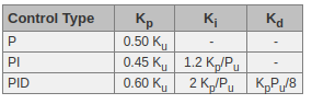
The derivative term is seldom used in practice and that's why I use a PI controller.The Ziegler-Nichols method for PID tuning offers a bit more structured guide to setting PID values. Again, you’ll want to set the integral and derivative gain to zero. Increase the proportional gain until the circuit starts to oscillate. We will call this gain level Ku. The oscillation will have a period of Pu. Gains are for various control circuits are then given below in the chart.
![]()
An interactive example can be found here http://grauonline.de/alexwww/ardumower/pid/pid.html.
As Pu is hard to determine, the Ki can also be determined manually.
You should have an offset with P controller, it can not reach the set point as the error would be zero. This is fixed by the integral term.The PID controller is implemented but not fully tuned.
6. Tune the controller (in progress)
Other topics:
Kalman filter
I briefly looked into Kalman filter. This could be used to increase the way the position and speed of the rotor is measured.
This is only done if it is needed.In steady state, the speed is constant and our system is described with
the equationsHere p is position and v is velocity. With a Kalman filter, I could combine measurements to get a better estimate of the position and velocity, see source.
I foresee the following challenges;
- multiplications and divisions on a FPGA are complex (this seems required by the
Kalman filter)
- The measurement error is probably not Gaussian
As a result, Kalman filter theory might not apply.
My aim is to end up with a system in a very steady state. Rotor speed should be constant.
As a result, I would guess that even if Kalman theory applies. The Kalman gain should be constant.
So using Kalman theory for dummies, I simply assume![Kalman Filter - quick insight]() where Kalman gain K is a constant, I could try to figure out the best Kalman gain by simply trying some values and seeing what works best.
where Kalman gain K is a constant, I could try to figure out the best Kalman gain by simply trying some values and seeing what works best. -
Kingsburry Aerodynamic bearing
12/14/2022 at 10:34 • 6 commentsThe following video outlines the Kingsburry aerodynamic bearing.
The cool thing about it is that it does not require external pressure. It should be possible to produce it cheaply in bulk as glass syringes seem to fit the requirements. These are shown early on in the video, at around 10 seconds in. As the prism, is already out of quartz it cannot be hard to add this.


 where Kalman gain K is a constant, I could try to figure out the best Kalman gain by simply trying some values and seeing what works best.