 Domenic Rodriguez
Overview
The design was originally inspired by this circuit on EDN. The battery tester can test either a AA battery or a AAA battery. It is a constant current battery tester and draws 250mA from the battery being measured regardless of that battery’s voltage. Drawing a realistic load from the battery allows for a more accurate measurement of the remaining capacity of the battery. The tester is powered by a 9V battery, which can also be tested to ensure that it can supply power to the circuit. After inserting a battery to test, the LED bar graph will light up proportional to the battery voltage within a range of 0 to 1.5V.
Technical Description
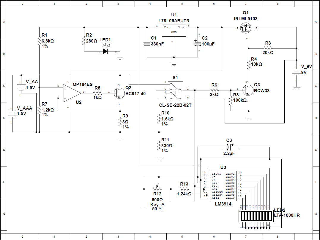
The circuit schematic is shown above. It can be roughly divided into the following sections:
- 250mA Constant Current Sink
- Power Regulation
- LED Bar Graph and Driver
250 mA Constant Current Sink
The current sink is comprised of an op-amp (U2) and an NPN BJT (Q2). Resistors R1 and R7 act as a voltage divider and set the non-inverting input of the op-amp to 0.75V. The inverting input of the op-amp is connected to the emitter of the transistor and to one terminal of the load resistor. The op-amp will drive the base of the transistor to keep its inverting and non-inverting inputs at the same voltage. R5 limits the op-amp output current. This results in 250mA being drawn from the input test battery through the transistor and the load resistor since 0.75V / 3Ω = 0.25A. The current is not dependent on the voltage of the input battery; the op-amp will drive the transistor to adjust for the voltage of the test battery and draw a constant 250mA. Two voltage sources are shown on the schematic to represent the AA and AAA battery inputs. In practice, only one of these batteries would ever be connected at a time.
Power Regulation
The LED bar graph and voltage divider are supplied with 5V using an L78L05 5V regulator (U1). This regulator takes 9V as its input. Transistors Q1 and Q3 act as switches to automatically turn on the 5V regulator when the test battery is connected. The positive terminals of the test battery inputs are connected through switch S1 to the base resistor of Q3. When this voltage goes high, Q3 switches on and in turn switches the MOSFET Q1 on, allowing 9V to connect to the 5V regulator and the op-amp. LED1 serves as a power indicator for the 5V regulator, with R2 limiting the LED current.
An additional feature of the battery tester is the ability to test the 9V battery to ensure that it can power the circuit. R10 and R11 divide the voltage down to the 1.5V range, and S1 allows the circuit to switch from the input test battery to the 9V battery for testing.
LED Bar Graph and Driver
The last section of the circuit is the LED bar graph and driver. LED2 is a 10-segment LED bar graph used to indicate the status of the battery. The LEDs are driven by a TI LM3914 Dot/Bar Display Driver. This IC takes the input voltage from the battery, and using a series of ten internal comparators drives the output LEDs. The chip is set to LED bar graph mode by setting pin 9 (MODE) high. Resistors R13 and R12 set the LED current and control the input signal range according to the following equations:
R13 was selected as 1.24kΩ so that the LED current would be approximately 10mA. R12 is an adjustable trim potentiometer that is wired as a variable resistor. Ideally, it is set to 250Ω so that the reference voltage is set to 1.5V. However, the resistance can be adjusted from 0 to 500Ω so that the circuit may be calibrated to account for non-ideal characteristics in the actual circuit.
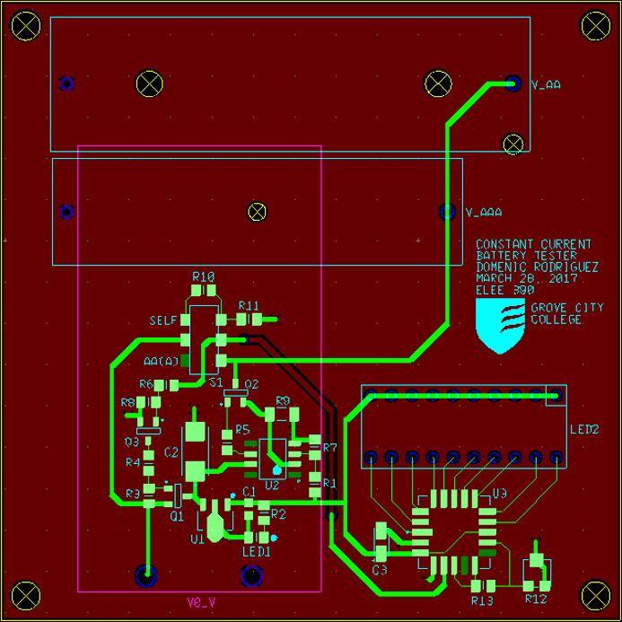
PCB Layout
The PCB layout from NI Ultiboard is shown below. The board utilizes a ground plane on the back layer with all but one signal routed on the top layer.
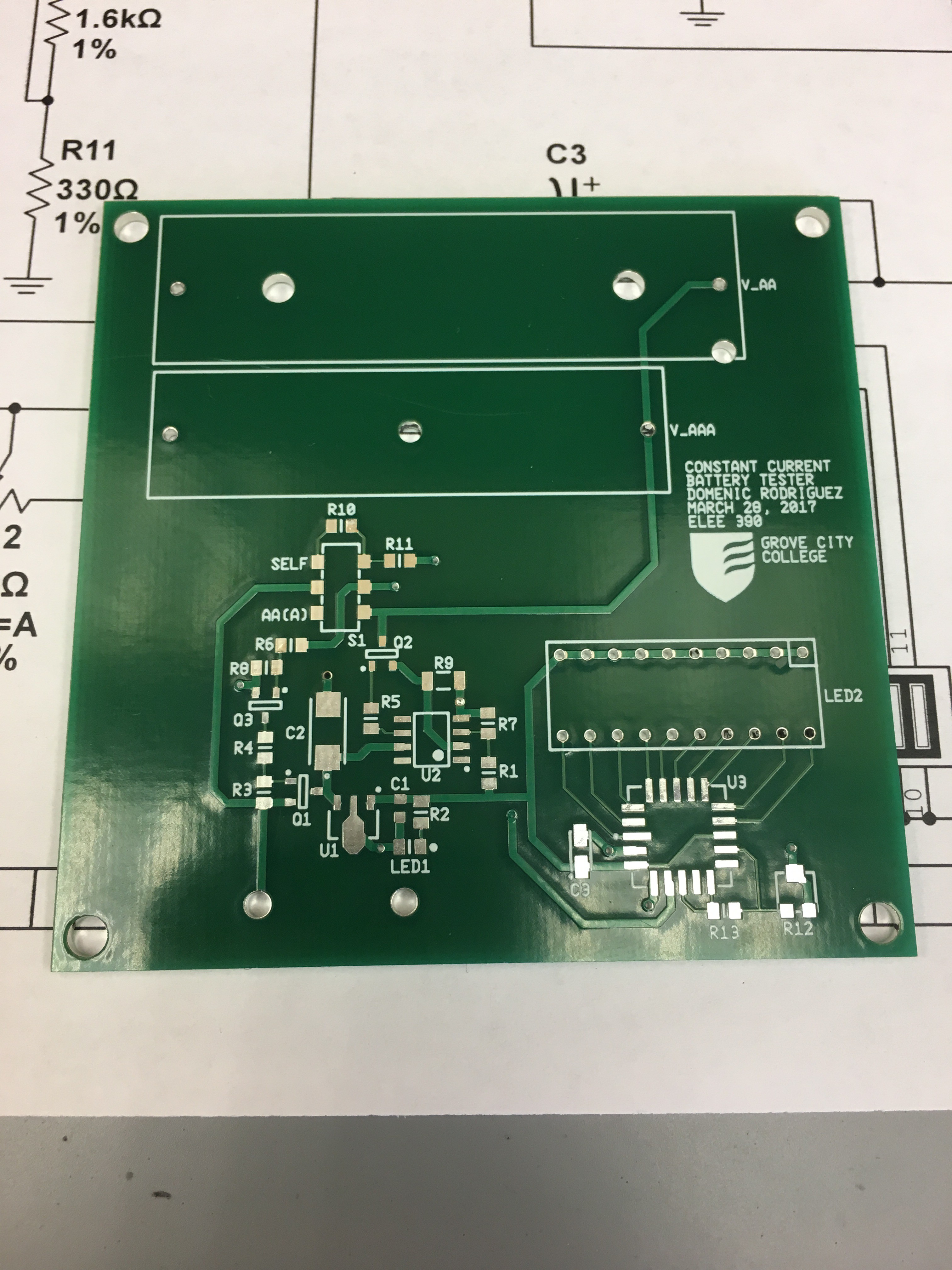
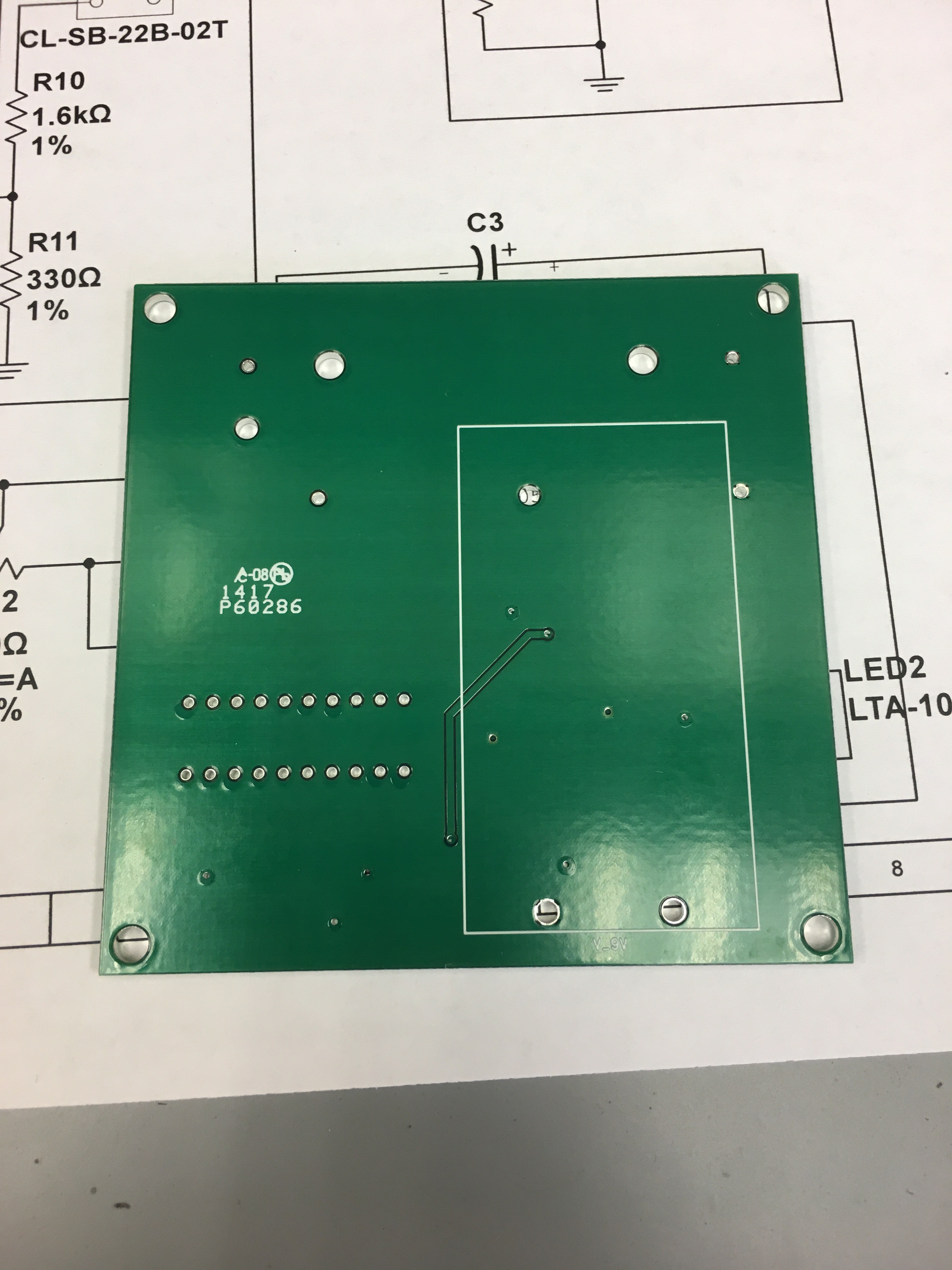
Assembly
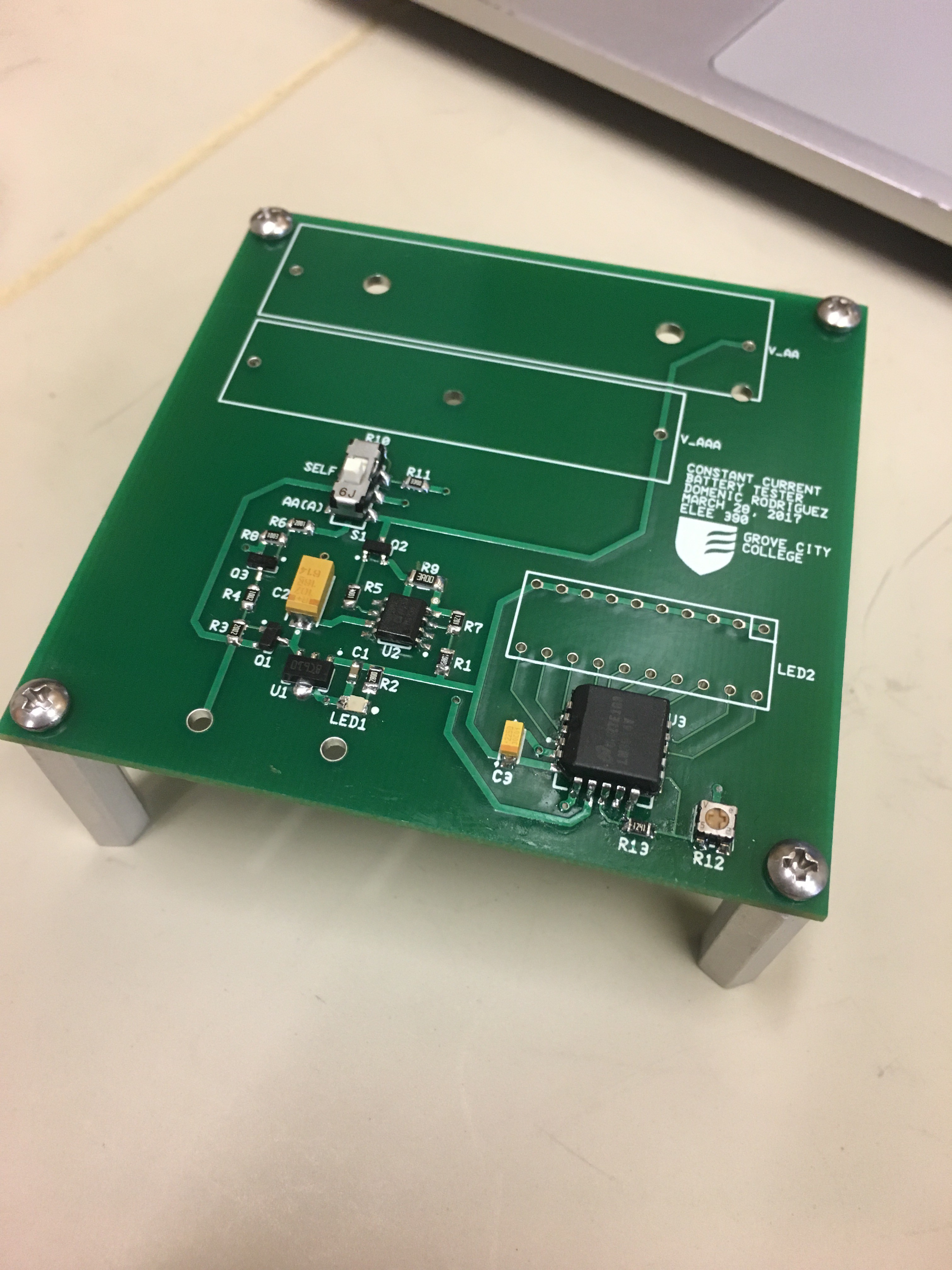
Here are the front and back of the PCB, fresh out of the packaging:
I started by hand soldering all of the surface mount components. Most of the components were not too bad, although the LM3914 PLCC20 package was a bit of a pain.
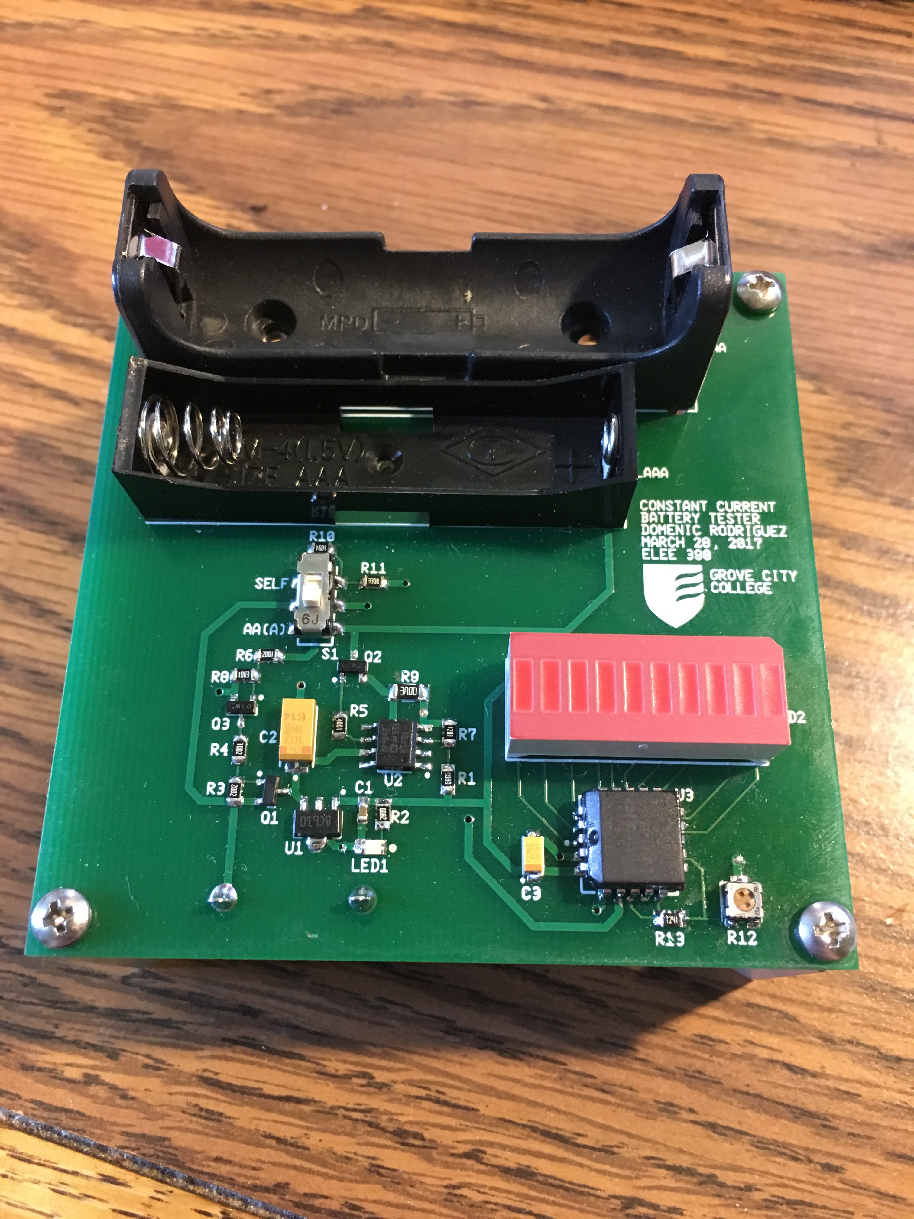
With all of the surface mount components soldered, all that remained were the through hole. Here's the fully assembled board:
Testing
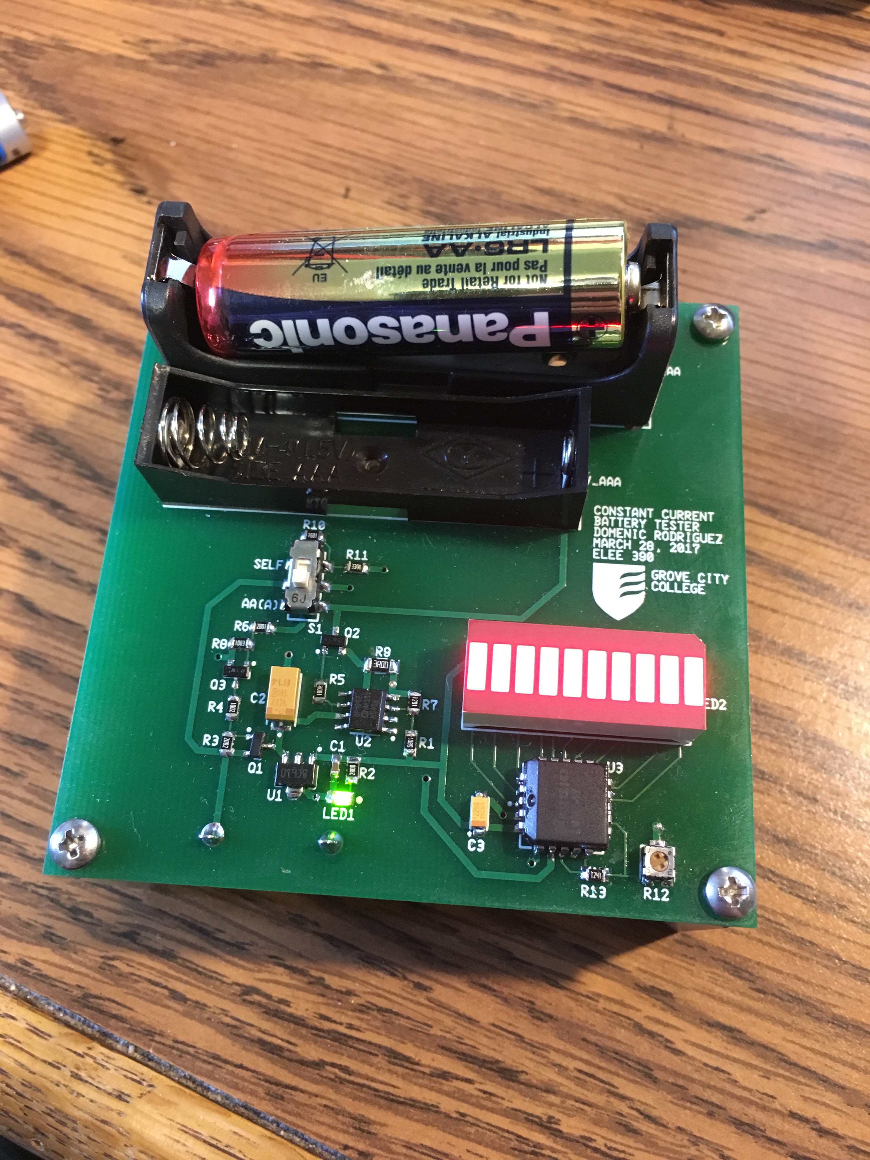
To my great surprise, almost all of the board worked on the first try! The green power LED (LED1) didn't light up at first, but I quickly found this was because I had a cold solder joint on the lower pad of R2. Here's the circuit in operation with a brand new battery:
And here it is testing the dead battery removed from my roommate's mouse:
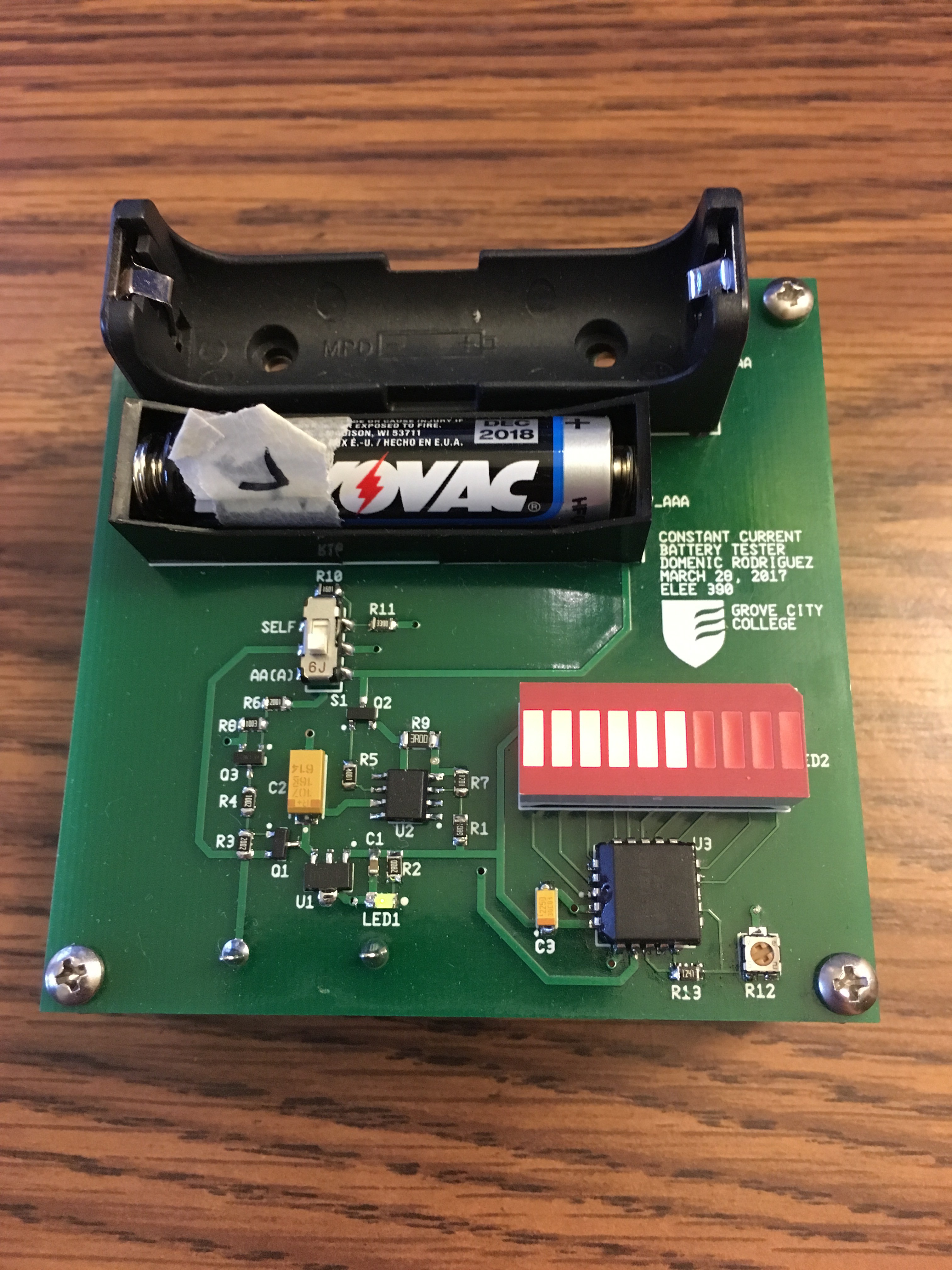
If this particular battery is left in place for too long, the LEDs eventually turn off completely as the battery is no longer able to supply enough current.
Results
Overall, this was a very fun introduction to printed circuit board design. It definitely payed off to be extra careful in checking all of the details (like the footprints) and reading the datasheets. Admittedly, this is a relatively simple circuit which made it much easier to get right. It was also interesting to work on an analog design instead of the usual digital circuits that occupy most of my time. I'm excited to take the skills I learned in board layout from this project and apply them to bigger, more interesting ones in the future!