 edensrock
As we mentioned in the previous updates, we are going to use LMX2594 in our final prototype. TI has just released the LMX2594 a few months ago. There is a relative small risk in using a newly released IC in the design. We wanted to mitigate that risk. We ordered two copies of the eval board (LMX2594EVM) and gathered a test setup to mimic ERASynth’s architecture. We needed two copies because ERASynth’s design uses one PLL for the reference generation loop and another PLL for the main synthesizer.
Test Setup
After establishing the necessary RF/DC/Control connections using appropriate cables, we powered up both of the eval boards using a low-cost switch-mode power supply (Gophert CPS-3205). LMX2594 requires only a single voltage rail of 3.3 V and draws about 400 mA. We disabled the on-board TCXOs of each board and supplied a reference of 100 MHz from the E8257D to the first LMX2594EVM (the reference generation loop). Normally signal generators are not as clean as crystal oscillators, but E8257D was sufficiently clean at 100 MHz. We fed the output of the first LMX2594EVM to the reference input of the second LMX2594EVM. Here is a block diagram and an actual photo of the test setup:
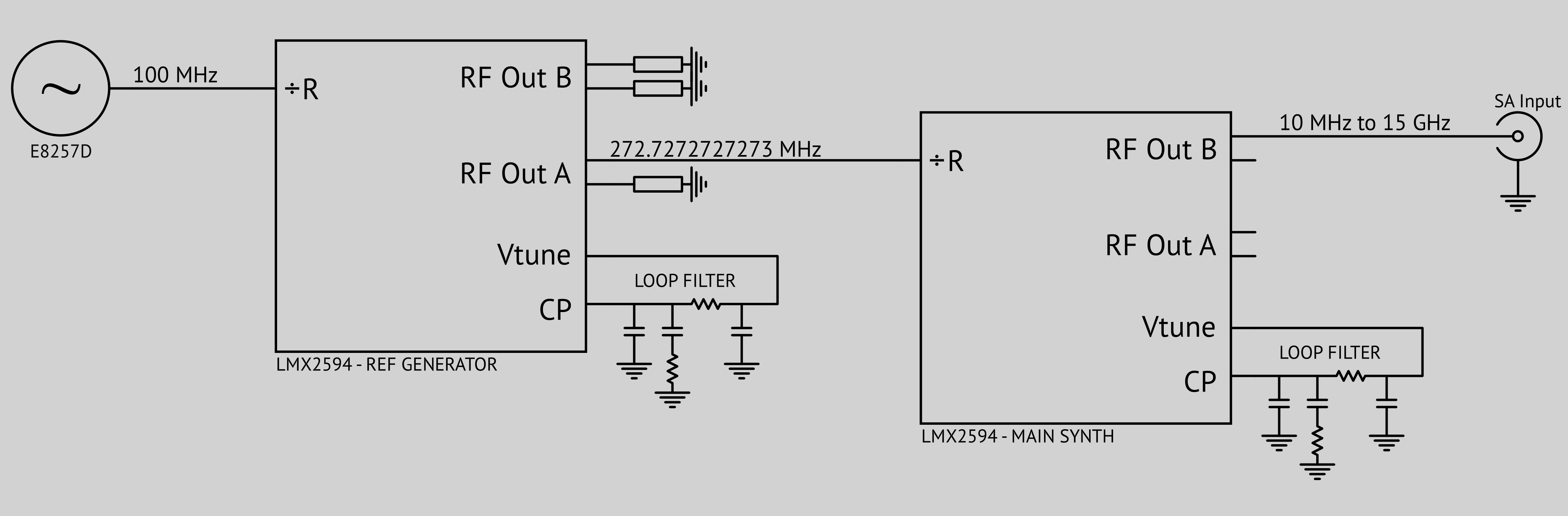
We drove one LMX2594 with another LMX2594 for ultra-low spurious.
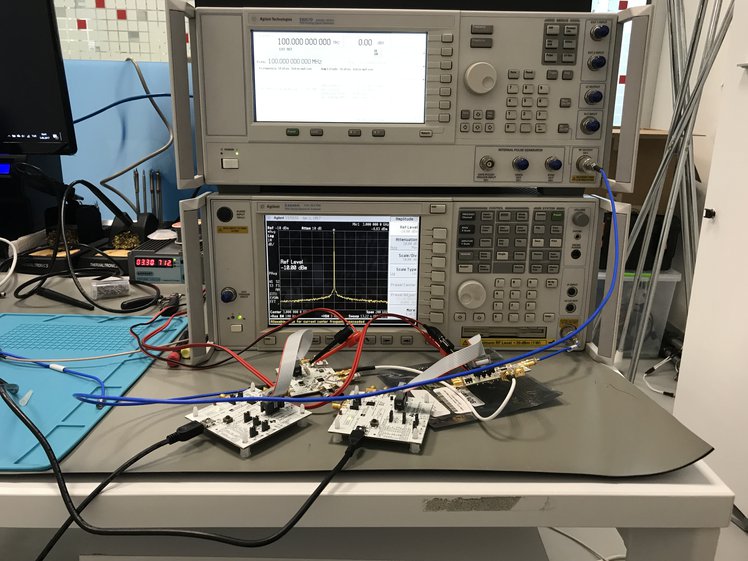
Photo of the Test Setup
As the block diagram shows above, PFD comparison frequency of ERASynth’s main loop will be around 270 MHz in the final prototype. This is a relatively high comparison frequency but LMX2594 can do it. In integer-N mode, LMX2594’s PFD rate can be set up to 400 MHz but there is a limit on the N divider (N ≥ 28), that is why we selected PFD rate as ~270 MHz.
Test Results
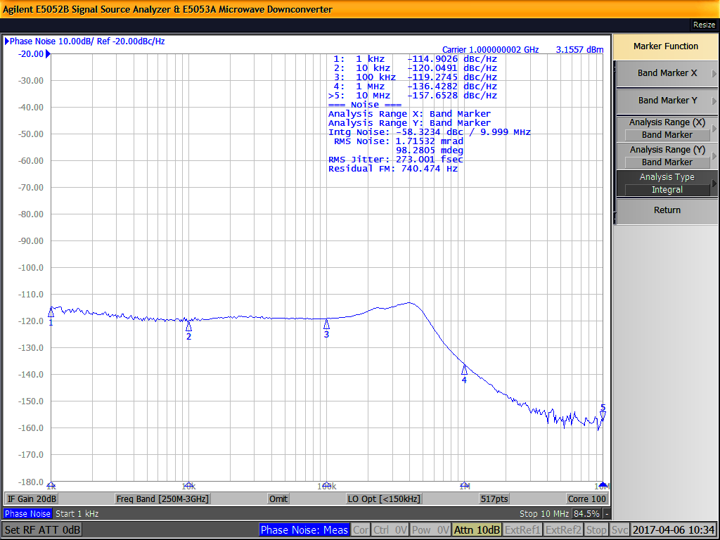
We measured a phase noise of -112.7 dB at 3 GHz, 10 kHz offset using our PSA spectrum analyzer. This value is a couple of dBs higher that what we were expecting. Obviously, there is some (about 3 dB) phase noise contribution from PSA’s tuning local oscillator. For exact measurement of such a low phase noise, we would need a signal source analyzer (SSA), which is a very expensive test gear. We took the phase noise graph shown in our campaign page with an SSA (courtesy of İTÜ’s VSLI lab).
We must say TI has done a great job in LMX2594. We went the extra mile in our second prototype just to get a phase noise of -120 dBc/Hz at 1 GHz. We had to drive ADF4356 with HMC830 while using LTC6945 as the external PFD. The people at the clock and synthesizers division of TI were able to squeeze even more performance into a single chip. What is more fascinating is that you can even feed this chip (LMX2594) with a switch-mode power supply.
Conclusion
Using two LMX2594 eval boards, we were able to verify the performance of ERASynth’s final revision to the best capability of our test equipment.
Discussions
Become a Hackaday.io Member
Create an account to leave a comment. Already have an account? Log In.
Hi Edensrock,
I am using LMX2594 for generating 13Ghz clock. But, when i change to 13.001GHz, a spur is show out.
Are you recommend idea for remove the spur.
thanks for your support !
Are you sure? yes | no