 Jorj Bauer
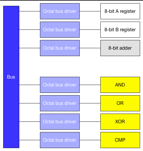
Having picked a crazy overkill instruction set, it's easy to see how those functions map out in an ALU. 2 registers; an adder; and four logic functions. I spent some time over the weekend thinking about how this maps out to a final design, and in particular realized that I've run a little short on a particularly important IC.
So, thinking a little about the adder, which should be fairly straightforward...
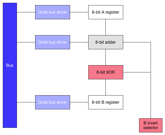
... where that XOR is the selector of whether we want to input B, or an inverted /B, so that we can subtract instead of adding.
But I only have two quad XOR gates - both of which I just bought, because I didn't have any in my original stock - which means I can either use them for the adder's "invert" operation selector; or I can use them for the XOR function itself.
Hmm.
If the ALU's XOR operation is supposed to be the A register XOR the B register, then there's no simple way to re-use those two ICs for both purposes. I could stick two octal bus drivers around it, selecting an output path to either the adder or the bus; and an input path either from the B invert selector or the A register.
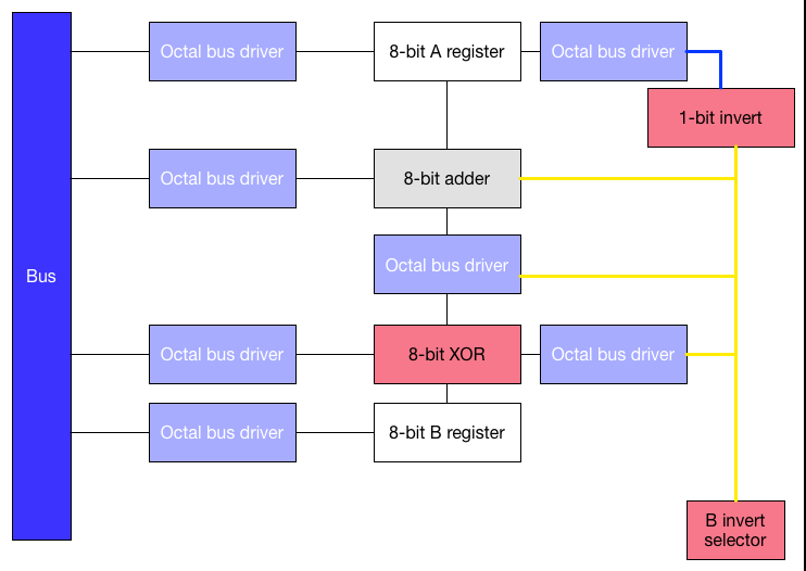
That doesn't feel like what I want, though. This is using a bunch of bus drivers for selection; it doesn't pay any particular attention to what other ICs I have lying around. Looking for another solution with the parts at hand, then... what if I use some of the multiplexers I've got to select either B or an inverted B as an input for the adder?
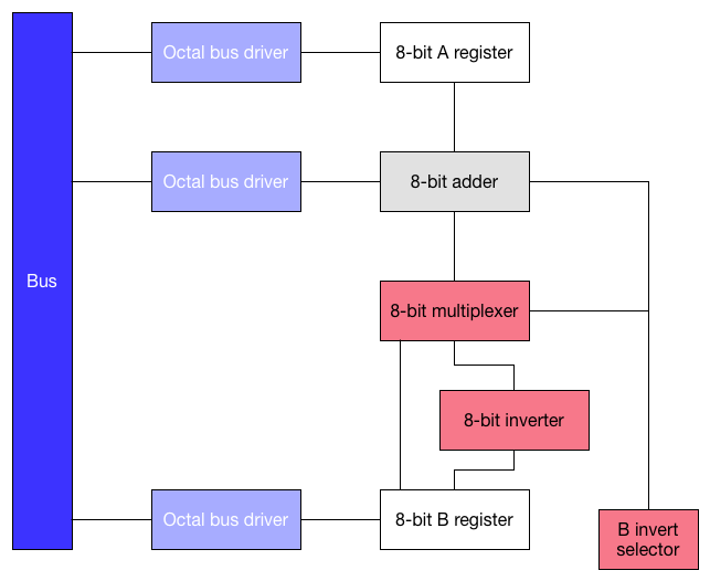
Ooh. That looks much sexier. A couple 7404 inverters to construct /B, and some multiplexers to select one or the other! I like it. But the devil's in the details: I have a rather motley assortment of ICs and I don't know that I have what I need. Or, rather, I know I don't have enough of any one part to satisfy that demand.
For starters: I have two 74LS153s. They work like this:
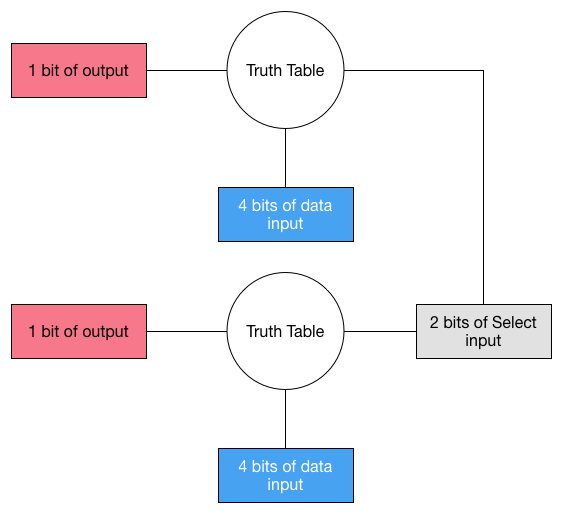
It's designed to pick one of the 4 bits of data input, in two places. I can use it like this, to select 2 bits from either B or the inverted B input:
And you probably now see just the level of crazy I'm going to with this plan. Since I have only two of these, I'll get just 4 of my needed 8 bits of virtual switch. Hmm. Well, I've got two 74LS151s, which are similar 1-of-8 multiplexers:
Well, I could use each of those for 1 more bit. Which gives me a total of 6 bits. Still not enough.
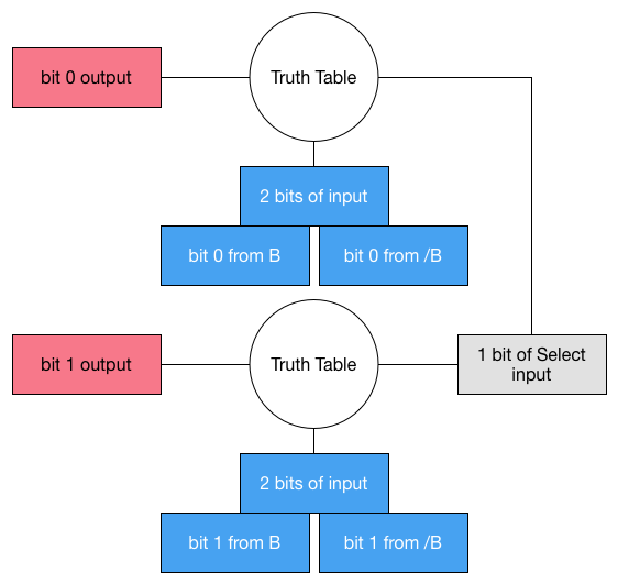
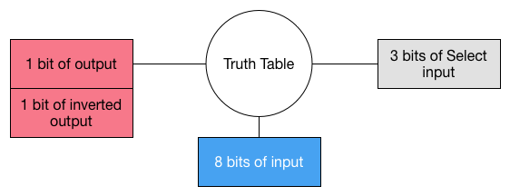
I've also got some 74LS139s, which are 1-of-4 decoders. A decoder is basically a multiplexer where the inputs are all logically tied high. The '139 inverts the output bits, which means it looks like this:
Hmm. If we add a NAND gate to the two middle bits of that output, then this looks like XOR. Which means that we can take one bit of B, and the B-Invert selector, we get two bits out which are either B or /B:
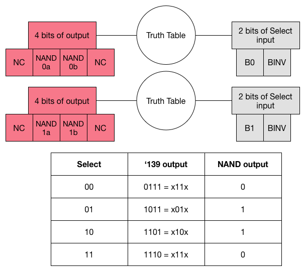
I feel like I just struck gold. I wish I had enough of those to build the whole 8 bits; this has a certain kind of sexiness to it.
But I don't have enough of any of those, so I'll have to mix-and-match.
I suppose I should try to minimize the board space used? I mean, I've already thrown in the crazy towel, so there's no sense trying to optimize for power draw, or number of ICs. Yes, yes, I'm looking for an optimization in some way other than "just buy two more 50-cent quad XOR ICs." I'll pretend you didn't even think that.
Since the 74LS151s would be mostly dead space - yielding just 1 bit of output each - I think I'd rather not use them. Which would mean using 2x 74LS153s; 1x hex inverter (using 4 bits to drive the '153s, leaving two inverters unused); 2x 74LS139; and 1x quad NAND gate.
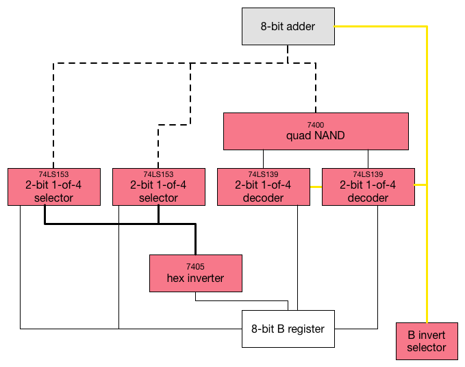
There's one final bit of insanity thrown in there. I'm running out of 7404 hex inverters... but I have five 7405 open-collector hex inverters. Which, if you add a pull-up resistor to the output, are basically the same thing.
Well, I guess this will be interesting to implement. I'm sure the wiring will be a nightmare, and if there are any problems with it, debugging will not be a barrel of monkeys. But it satisfies my design goal! Look at all those ridiculous ICs I'll finally be using for something...
Discussions
Become a Hackaday.io Member
Create an account to leave a comment. Already have an account? Log In.
Looks like a fun build! Unfortunately I don't have so many '153s, which is what lead to this crazy design. The classic "use whatever crap I have lying around" design. But it's a really good point that the thing I designed is just a baby step along this road. Perhaps I can come up with something more clever with the two '153s and two '139s...
Are you sure? yes | no
You can make an 8-bit ALU out of 2* 74'283 adders and 8* 74'153 multiplexer chips, for 10 chips total. See https://hackaday.io/project/20781-breadboard-color-computer-from-ttl (in the older blog I started with an older design but I switch to the '153-based later on).
The ALU design itself is described here http://6502.org/users/dieter/a1/a1_4.htm and http://6502.org/users/dieter/a1/a1_6.htm
For my system I just left out the last stage with the '157, so I don't have "right-shift".
Are you sure? yes | no