 Jorj Bauer
I'm starting to find I'm running out of parts! After designing two parts of Detritus to use the exact same chip, which I only had one of, I figured it was time to start laying out everything to figure out what's actually remaining.
Starting with the ALU, it's straightforward to lay out what I've got. Bus drivers. Mismatched AND and NAND gates with an inverter. OR gates. XOR gates. Comparators.
And that's where it becomes a little fuzzy.
I've not thought much about the output display, although I have a couple 7-segment displays, and an 8x8 LED matrix. Driving those is a little more complicated. The program EEPROM; Instruction Register; control circuitry. These need work.
So, moving on to the displays, then.
To drive two bytes of 7-segment display, I could take two 4-bit registers; feed each one in to a single EEPROM; and feed the output in to one of the 7-segment displays for each Hex digit. Simple enough.
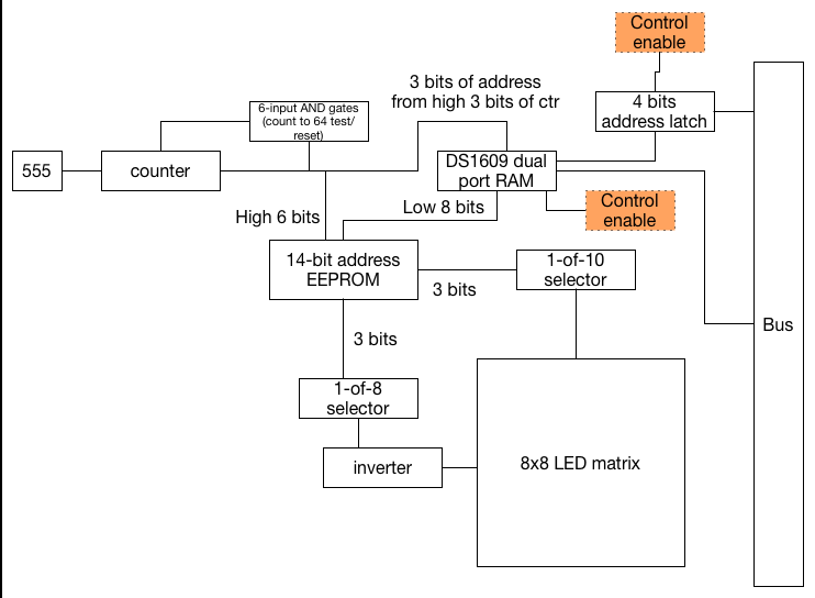
For the matrix, though: I want to be able to individually turn on each of 64 LEDs. I suppose that means an EEPROM acting as a logic translator - but it would need to be 16 bits wide, to drive the 8 cathodes and 8 anodes in the matrix. Unless I do something clever.
I only need to enable one cathode and one anode at a time. Which means I could use 1-of-8 selectors to drive the one, from 3 bits of input each. So with 6 bits of input, we'll get one LED of output.
But I don't have two 1-of-8 selectors. I've got one. And a 1-of-10. That'll do.
The selectors invert the output, which is great for the anode side of the LEDs. For the cathode I'll need +5v out, which means 8 inverters. I've got some 7405 hex inverters I can use. And that's enough for turning 6 bits of input in to one LED of output - but I still need to get those 6 bits of data.
Well, if I take the 8 bits of data being input; 3 bits of "which row is this"; and 3 bits of "which LED in that row is the one I'm currently trying to light up" - then we can take a total of 8 bytes of input and turn them in to each of the 64 bits of output individually, in sequence.
That all means a 555 timer that's feeding an adder which resets at 64 (counting from 0 to 63); some sort of RAM to hold the 8 bytes of data; and a way to program it from the bus. Well, that last bit is a little difficult; if the data from this RAM is tied to the EEPROM and a timer/counter, then I'll need some complicated logic to decouple it when the RAM needs to be updated with new values.
Unless.
There's a type of RAM that's designed just for this - dual-port RAM. A dual-port RAM has two distinct busses - and either side can read or write at will, independently. I only need 8 bytes, a very modest dual-port RAM. Perhaps I can find one on eBay cheaply.
If this is how it plays out, then the design looks something like this:
Time for some parts shopping, then. I need a larger EEPROM. I've already run out of latches. And I need a dual-port RAM.
Perhaps the whole thing winds up looking like this, then...
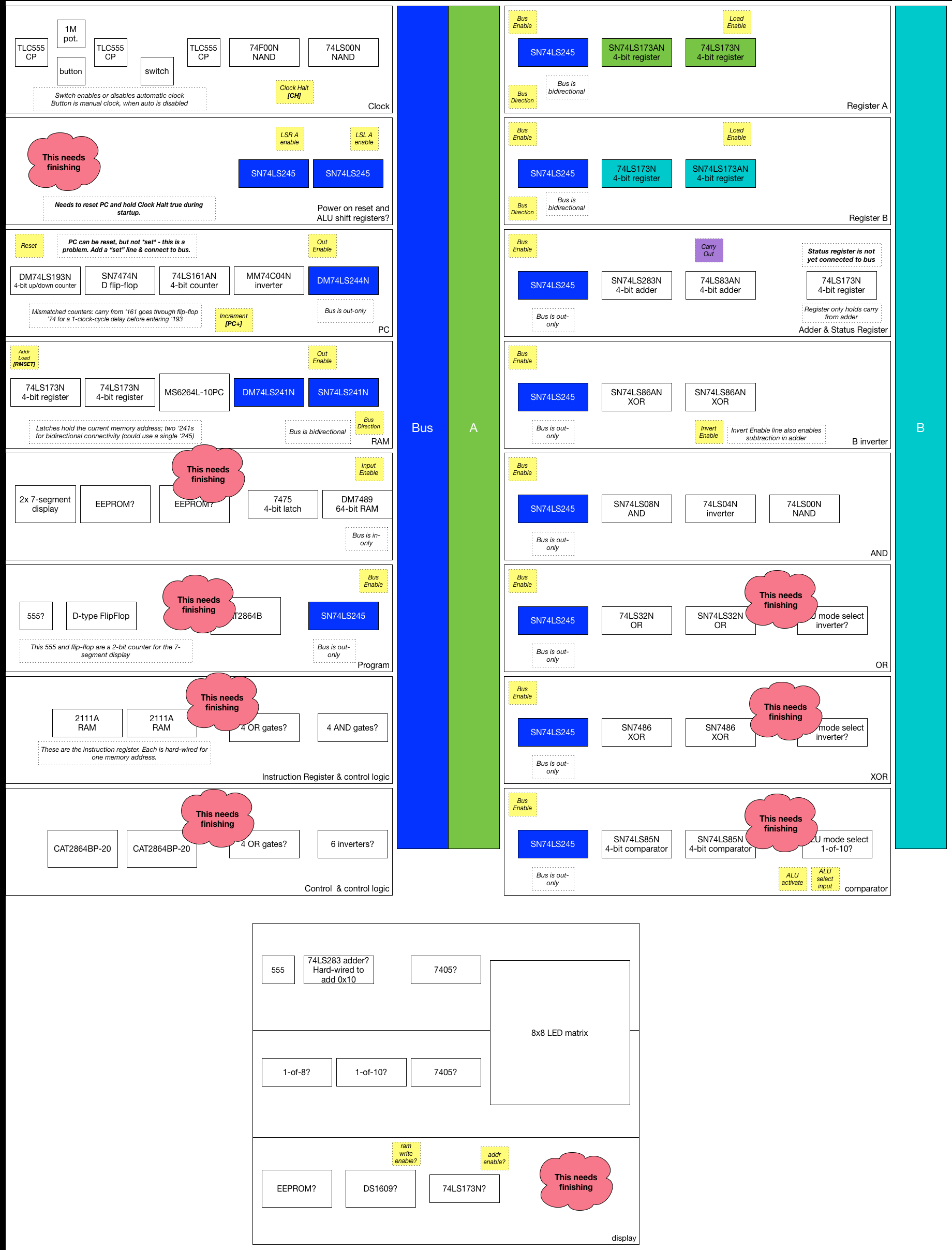
... lots to do there!
Discussions
Become a Hackaday.io Member
Create an account to leave a comment. Already have an account? Log In.