 matt venn
I got to the point of tuning the PID loop and found the RPM counter had stopped working - the RPMS went up as the motor slowed down!
I checked the signal (while rotor was still) on the scope:
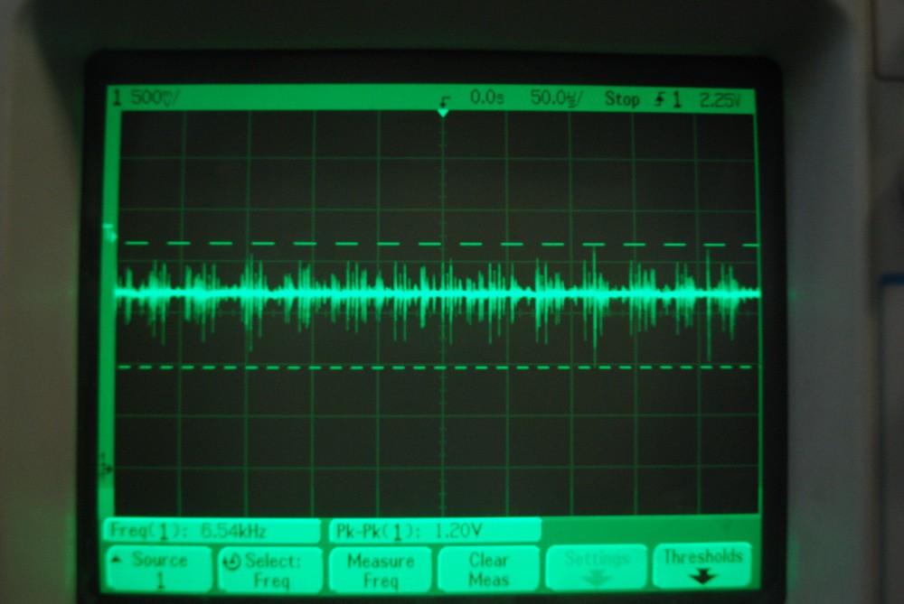
And found a lot of noise. So as the white band passes by the opto, not one count is recorded, but many. And the slower the rotor, the more the noise affects the count.
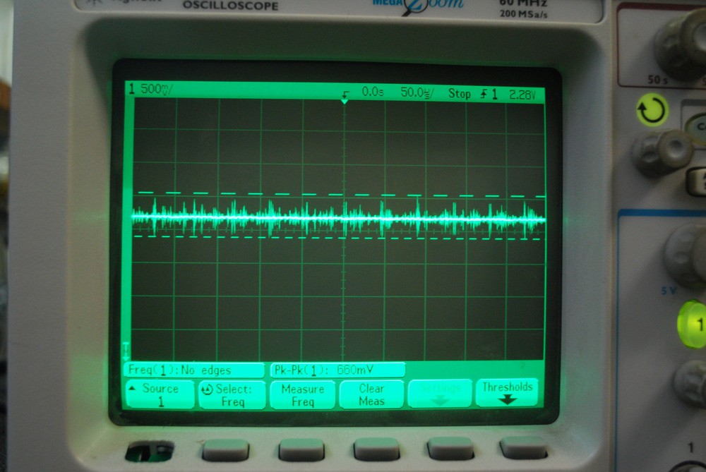
Tracing this back I checked the Arduino +5v supply:
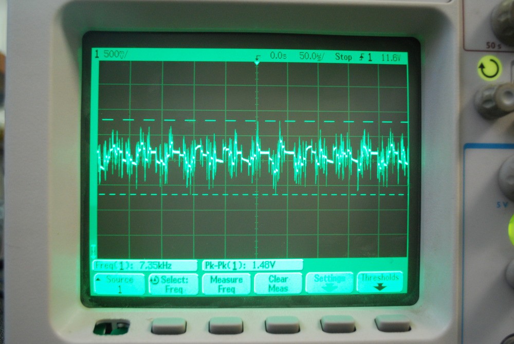
And then the 15v motor PSU:
Finally, I checked the 15v motor PSU with the steppers disconnected:
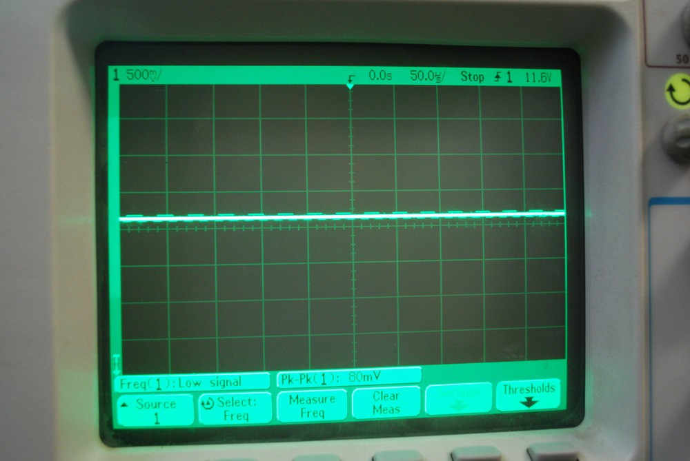
With either the motor PSU disconnected or the PSU on but steppers disconnected, the RPM counter works.
The stepper driver boards have 2 supplies, one for logic and the other for motor. The motor control signals are all opto isolated. I measured for continuity between the 2 grounds (logic and motor) and they are not connected.
I can understand why there is a lot of switching noise on the PSU when the motors are on, but I can't understand why the noise would make it into the other PSU when they are isolated. I've tried a few different sizes of caps on the 15v motor PSU but they hardly help at all.
Can anyone help?
Discussions
Become a Hackaday.io Member
Create an account to leave a comment. Already have an account? Log In.