 matt venn
I finally got round to some testing and loop tuning. I did some no load tests where I changed the speed, and some tests where a load was applied at 2 different RPMs.
The graphs are produced by a python library called matplotlib that can do animations, so I got to see these happening realtime - which made loop tuning a lot easier. The program is called plotter.py and is in the code repo.
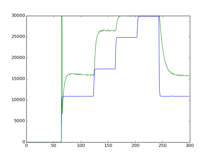
The blue line is the desired speed, and green is measured RPM. Time is rather confusingly done in samples which are 4 per second, so 40 samples is 10secs.
First up is the RPM change with no PID. I didn't expect the two to match up, as there is no feedback. But it's interesting to see the response time.
And here's with PID:
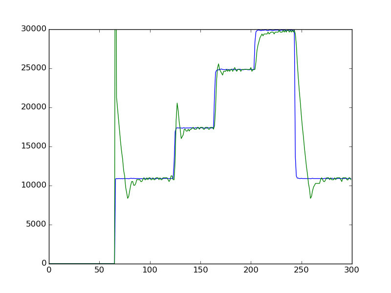
Where you can see the overshoot. I chose a fast response, which means that some overshoot will happen.
Now here's with a load applied. The load test was as followed: I put a broken bit in upside down, so there was a smooth steel rod spinning in the router. Then I put a lever on the bed. It was attached 40mm away from the router bit, and then 130mm from the pivot I hung a 115g weight. These numbers are arbitrary, I just had them to hand. The important thing is to be able to reproduce the test at a later date.
Again, first is without PID:
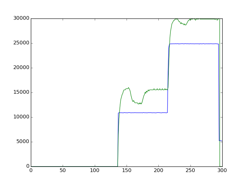
You can clearly see where the load was applied, and the change in RPM. Especially when at lower speeds, the load makes a bigger difference - which is why without the closed loop control I can't do slow RPM machining.
Now here's with PID:
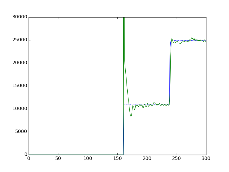
It's difficult to even see where the load was applied. But you can see where it was removed because of the slight overshoot.
So a success! The last thing I want to do is try doing some machining at low RPMs with aluminium and low melting point plastics.
Discussions
Become a Hackaday.io Member
Create an account to leave a comment. Already have an account? Log In.