 matt venn
I was expecting to just steam roller the triac, zero cross and opto spindle detector and get on to the juicy PID. But the zero cross circuit took at least 4 hours of debugging to understand and get working. I had just copied this circuit, which has a great description of how it works too. I didn't bother to understand it, just put it in my schematic and had the pcb made.
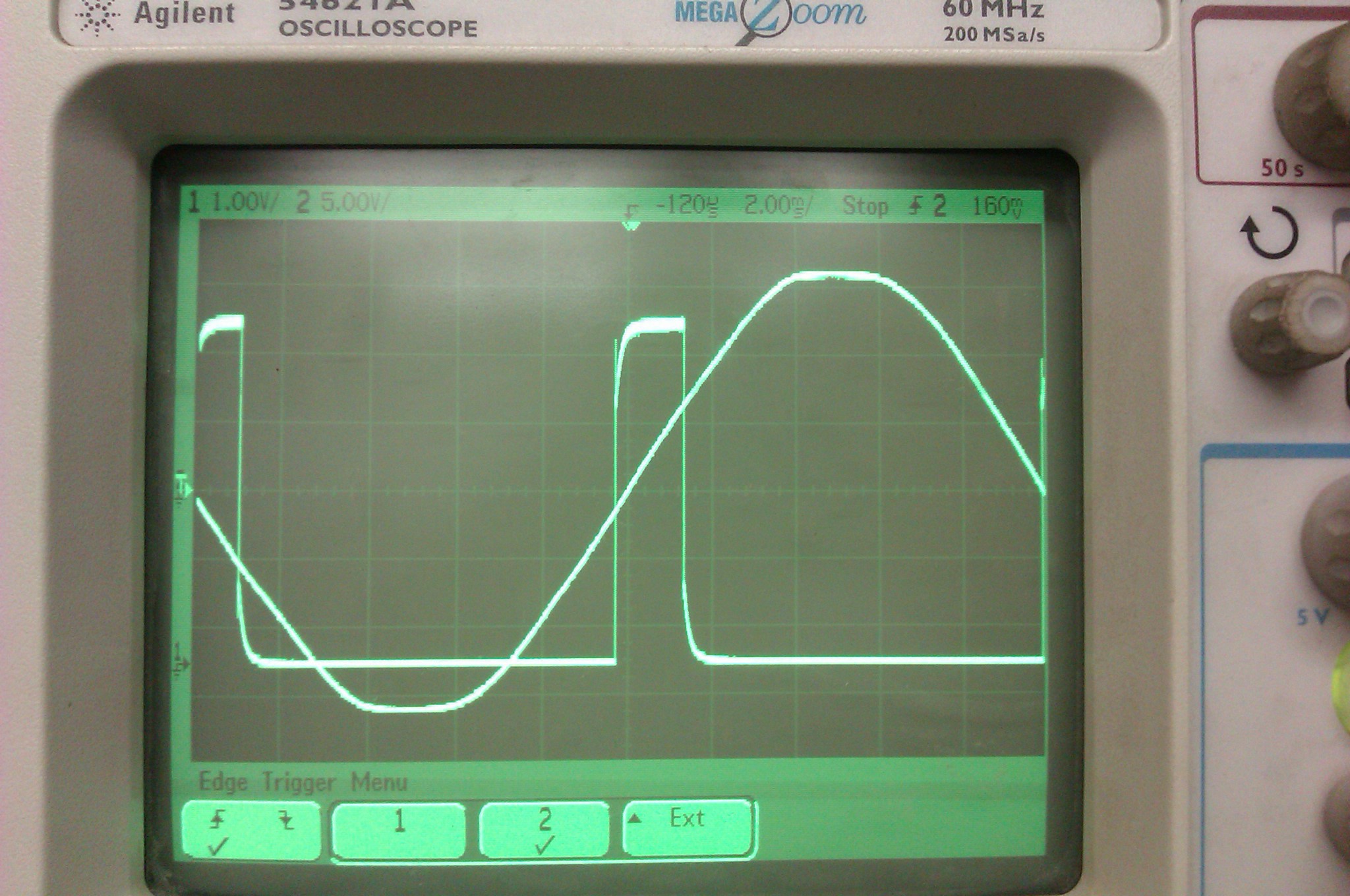
Things seemed ok (no fire or smoke), but I didn't get any pulses out of the opto isolator. I was a bit hesitant to use the scope on mains (240VAC in the UK) but I got over that and soon was checking the wave forms. In fact, after the first 2 large resistors, the voltage is only about 16VAC.
I still couldn't understand why it wasn't working so I downloaded a (terrible) simulator and modelled the circuit. The thing I was missing was that the diode under the capacitor let's us compare "0v" with the incoming sine wave of the mains. I'm putting 0v in quotes because with AC we have to pick some voltage we're calling 0v. Then the transistor should switch on when the voltage on the diode becomes more negative than the voltage stored in the capacitor. I've got some photos of the scope during the investigation on the schematics github.
I could see this happening on the scope, but the transistor wasn't switching. The first circuit board I ever made didn't work because the footprint of the NPN transistor I was using was different to the one I'd used in the pcb program (Eagle). On a hunch I tried a different transistor and I got some results!
Still not great though, the wave form wasn't square at all, and trying to use it on an interrupt pin on the arduino wasn't going to work. I went back to the schematic, and also re-read the info on the ZC page (linked above). Although I'd put a footprint for the pull up resistor on the output of the opto isolator, I hadn't placed it - instead using an internal pullup inside the Atmel chip on the arduino. It turned out this isn't a pull up resistor, it sets the current through the opto transistor inside the opto isolator! So having a 20k odd resistor wasn't allowing enough current to saturate the transistor. It was behaving as an amp, not a switch. Well, kind of in between.
Placing the resistor, and setting it to 5k (as in the original schematic) solved this, giving me clean, square, fast pulse that started just before and ended just after each ZC. Perfect!
Discussions
Become a Hackaday.io Member
Create an account to leave a comment. Already have an account? Log In.