Close
0%
0%

Spider, a Tiny Home Automation Hub

Low-cost modular MQTT devices

Similar projects worth following
Smart devices in the home often still lead to a Basket of Remotes rather than an Internet of Things. It's not that devices don't communicate, it's that they don't communicate with each other.

Spider addresses a part of this problem. It is a tiny PCB that combines WiFi, infrared, a 433 Mhz transmitter and nrf24L01+ transceivers and can act as a bridge between MQTT networks and other protocols. Spider can be used to connect devices to MQTT that originally only communicated with their own remote controls.

Additionally, due to its expansion port, the same PCB can be used as a sensor board to create small, low-power devices that use a Spider hub to communicate with those same MQTT networks.

The intended setup for the spider board is to have one or two fully populated boards that act mainly as WiFi-NRF bridges for MQTT messages. Other instances of the board have less communications hardware and are typically intended as single sensor/actuator boards.

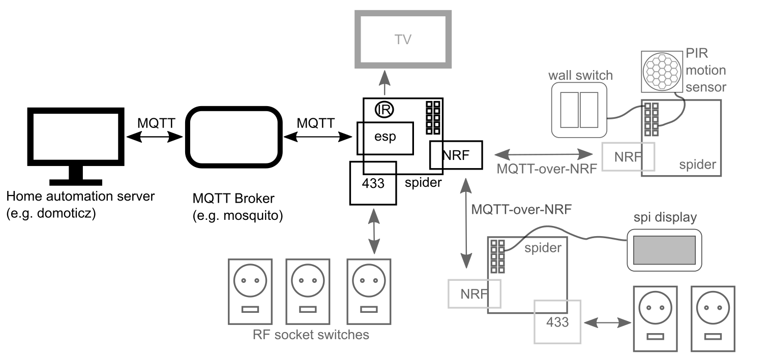
Many of my AVR-based projects have required some form of wireless communication at some point. Adding communication options is made fairly easy by readily available components such as the ESP8266 or NRF24L01+ modules. However, breadboarding or experimenting with such devices typically offer a few hurdles; they're 3.3v and often have pinouts that are incompatible with breadboards.

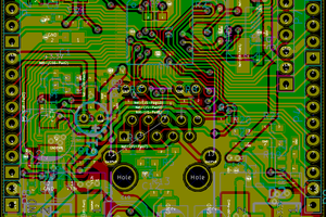
This is why I decided it would be convenient to have a single PCB that combines all the communications modules that I've got some experience with:

  • esp8266 WiFi module
  • NRF24L01+ 2.4 Ghz transceivers
  • 433 Mhz transmitter module
  • IR-LED and receiver

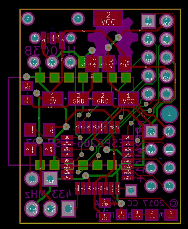
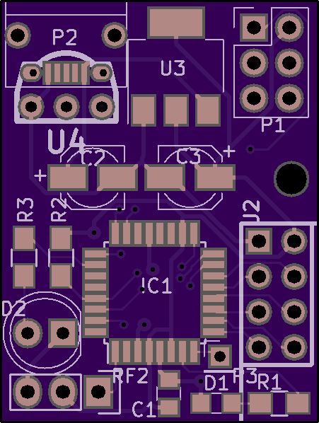
The board has a row of headers to break out some of the AVR GPIO pins. Power is supplied via a micro-usb connector and regulated down to 3.3V with an AMS1117, but can also be provided through the header pins for battery-operated projects.

This was a first exercise in creating a double sided PCB and therefore I also didn't etch the board myself, but had the PCB produced through OSHpark. Because the cost is directly related to the size of the PCB, I've also tried to make this board as compact as possible.

Most of the network related stuff is already taken care of by the excellent esp-link firmware. Stubborn as I am, I decided that my "raw" (non-arduino) AVR firmware could not use the arduino client library for the esp-link and therefore I needed (or somehow wanted) to write my own "raw AVR" esp-link client.

The AVR runs an optiboot ("arduino") boot loader, so that new AVR firmware can be flashed over WiFi, again thanks to the esp-link firmware. It would be nice if it were also possible to update the AVR firmware over NRF, so that the "dumb" sensor boards can also receive firmware updates remotely, but this requires some serious re-writing of the boot loader.

All dedicated firmware for this project is licensed under the Boost Software License version 1.0, while the dedicated hardware is available under a Creative Commons Attribution-ShareAlike license.

  • 1 × Atmega328 Microcontroller
  • 1 × NRF24L01+ 2.4 Ghz transceiver
  • 1 × esp-03, ESP8266 module
  • 1 × IR-led
  • 1 × HS0038 or equivalent IR-receiver

View all 7 components

  • Using node-red for advanced automation

    Danny Havenith06/25/2017 at 22:46 0 comments

    How weird, things are getting useful. This project is all about integrating powerful components of others and Node-RED is a good example of such a component:

    Read more »

  • Connecting Sensors and Switches

    Danny Havenith06/11/2017 at 22:04 0 comments

    Today, two spider devices communicated with each other for the first time, and it worked! In this setup, an AVR with IR sensor detects motion at the front door and signals this to an MQTT broker. A Spider device listens to the message and switches on a light inside the house using an RF socket switch. Schematically:

    The following video shows the system in action.

    Read more »

  • Switching lights with MQTT

    Danny Havenith06/10/2017 at 22:44 0 comments

    MQTT is working!

    Spider can now successfully subscribe to an MQTT topic and switch RF wall switches.

    There are still some hard-coded constants that need to become configurable in EEPROM in the future, but in essence switching the lights works as intended.

    Read more »

  • esp-link MQTT software

    Danny Havenith05/28/2017 at 19:46 0 comments

    Spider uses esp-link for its wifi connectivity. This custom esp8266 firmware offers many functions in addition to plain network connectivity. The one feature that was very useful from day one was the AVR firmware update: An avr with a suitable boot loader can receive firmware updates over WiFi via the esp.

    Spider uses the optiboot boot loader. This means it's flashable through its serial port. It should even be possible to flash a Spider board from the Arduino IDE, although most programs will probably not work as expected due to the 8 Mhz clock.

    Another nice feature of esp-link is that it can take care of maintaining a connection with an MQTT-broker. It allows the AVR to publish messages and to subscribe to topics. The AVR and esp-link must use the SLIP protocol in order to have both plain serial communications and in-band esp-link commands on the same serial port.

    For Arduino, there is already an esp-link client library that takes care of the SLIP communications and the format of the command packets that are sent from and to the esp-link. Stubbornly, I decided that this library could not be used for Spider:

    • The Arduino library depends on the Arduino environment and, for instance, the Arduino serial port. This would mean that in order to use the library, I'd have to use the Arduino environment and somehow adapt for the 8Mhz clock. All in all not impossible, but quite an undertaking. Additionally I have some fears that depending on Arduino libraries would cost me more program space and RAM than I have available (Spider uses an Atmega328 or Atmega88).
    • Although the esp-link client library is well-written, it is written in C++'03. C++11 offers features that make programming for microcontrollers a lot easier and I thought it would be a good exercise for both the modern C++ muscles and the microcontroller C++ muscles to write my own version.

    In other words: I'm a walking example of the NIH syndrome.

    The library is still a work-in-progress. As always, writing my own version of this library took way more time than predicted. It has also taught me a lot about how the esp-link firmware works though, so in the end I don't consider it a complete waste of time.

  • Hardware revisions

    Danny Havenith05/20/2017 at 21:53 0 comments

    The PCB has undergone some revisions since I've started the project:

    Version 1 was the first board ordered from oshpark:

    This board works OK, but had a few issues:

    • I had forgotten to pull down GPIO15 on the ESP. This means the module won't boot properly and this had to be fixed with a patch wire
    • I used a TSOP2438 footprint for the IR receiver, but I found out I had a HS0038. This meant I had Vcc and GND reversed. This was easily fixed by bending the pins on the receiver and adding some heat shrink to prevent shorts.
    • The micro-USB-B connector is supposed to stick out about 1mm from the board, but I had aligned it with the edge. This meant that the connector is pushed up a little at the edge.
    • The 433 Mhz transmitter was powered from 3.3V regulator. Presumably 5V would give better signal and from previous experiments I knew I could power it at 5V and still signal it from 3.3V.
    • Some weird conflict occurred between the ams1117 on my PCB and the one on the USBasp AVR programmer, which broke the 3.3V power on the USBasp. All of this happened with no power applied to the spider board.

    Read more »

View all 5 project logs

Enjoy this project?

Share

Discussions

Similar Projects

Does this project spark your interest?

Become a member to follow this project and never miss any updates