 J. Peterson
After designing the Curilights, I wanted a way to easily control them without a computer attached. I came up with this controller, based on the mbed platform. The controller:
- Stores light patterns on an SD Card.
- Connects to a computer via USB for uploading patterns and animations.
- Has a menu driven UI with an LCD display for choosing color, brightness, patterns, and options.
- Optionally turns the lights off when the room is dark and no motion is detected.
- Turns the lights on if the room is dark and motion is sensed (night light mode).
The LCD user interface is based on a simple knob input. Turn the knob to change choices and push to make a selection. Using the knob is (like the iPod) immediately intuitive.
Controller Design
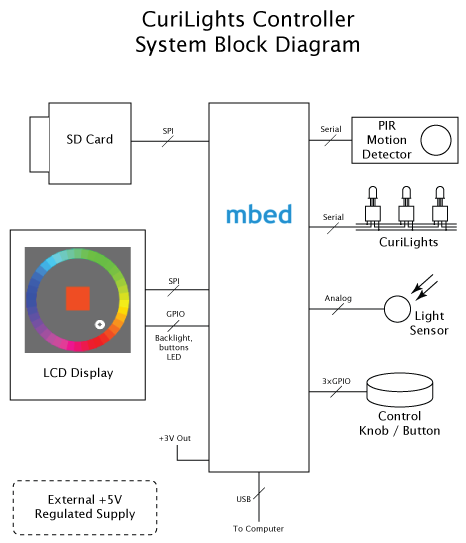
One of the benefits to using a MCU like the LPC 1768 is its ability to drive a full color raster display. This makes for a much cleaner and more intuitive user interface. For this system, a 1.5" Epson color LCD display is used for displaying menus and graphics. The primary interaction with the controller is a knob attached to a rotary encoder. Knobs make ideal controls, because it's easy to quickly turn past unwanted selections, yet easy to get fine control for desired ones. The knob also features a push-click momentary switch useful for confirming selections.
An SD Card is included for storing a catalog of patterns. This provides a straightforward way to update or add to the collection of patterns in cases where the controller is permanently mounted away from easy computer access. The USB port on the mbed module is also used for a couple purposes. First, the serial input connection is routed directly to the serial input on the string of lights, allowing the light string to be controlled directly by an attached PC. Second, new patterns may be downloaded via USB to the disk drive on the mbed. When the mbed is reset, any patterns downloaded on it's internal USB drive are moved over to the SD card for access by the controller.
Finally, two sensors on the controller monitor the lighting environment so the controller responds appropriately. A photocell connected to one of the mbed's analog inputs measures the ambient room light, so if the room is dark, the lights are shut off. A PIR (Pyroelectric InfraRed) motion sensor, however, “wakes up" the lights if motion is detected, making the system useful a night light.
Hardware
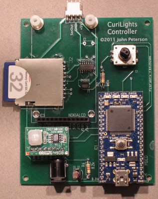
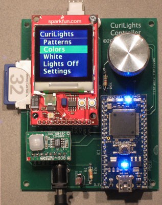 Figure 4 - a) System Board, b) With
Display Attached
Figure 4 - a) System Board, b) With
Display Attached
The heart of the system, of course, is the mbed development board, based on the NXP LPC 1768 MCU. The rich set of on-board peripherals, timers, interfaces and memory all find use in this project.
The LCD display is an Epson LCD originally manufactured for Nokia 6100 series phones. Because of the tremendous volumes phones are manufactured in, these displays are now relatively inexpensive. This display comes mounted on a breakout board from SparkFun electronics. The breakout board simplifies the physical assembly and provides some additional circuitry for powering the display's backlight.
The display communicates with the MCU via an SPI interface using mbed pins 11 and 13, pin 14 is used to drive the display's CS (Chip Select) line (note the display is a “write only" device). The SparkFun breakout board has some additional peripherals including an RGB LED and two pushbutton switches. These are interfaced to the mbed, via GPIO lines. Although the current system doesn't use these, they may become useful as the software design evolves, so it made sense to wire them up.
The display's backlight is driven via one of the mbed's PWM (Pulse Width Modulation) lines. Using a PWM line allows the mbed to gracefully fade the display on and off. Since the backlight requires 5 volts and a significant amount of current, a 2N3906 transistor is used to switch the current for this line. In order to drive the transistor to saturation, the mbed output is run through a TI TXB0104 level converter to take the 3.3V output of the MCU to the 5V level of the backlight supply line.
The motion detector is a Zilog ZEPIR0AAS01SBCG. This is a self contained unit with its own MCU. It communicates to the mbed with a simple serial protocol on pins 27 and 28.
Most of the other components interface very simply to the mbed. The SDCard adapter is connected to the SPI port via pins 5 – 8. The photocell forms a simple voltage divider and is fed into an analog input line, pin 19. The rotary encoder knob uses three digital inputs, one for the pushbutton switch and two for the quadrature – encoded rotation signals. Finally, a serial port on pin 9 is used to drive the CuriLights. Since the CuriLights run on 5V, another channel of the TXB0104 level converter is used to interface to them.
Although the USB port is integral to the mbed module, it also forms a key piece of the overall hardware system. The serial input is used to pass data from any attached computer on through to the CuriLights, allowing the controller to operate as a USB to serial interface. And lighting pattern files downloaded to the mbed 's USB storage are automatically transferred at system start to the SD Card, where they're used by the system.
Schematic

Software
The basic structure of the user interface is a menu using the knob to select items, pushing on the knob when the desired selection is reached. This UI is immediately familiar to anybody who's ever used an iPod® or most any digital camera.
Familiarity with these devices has also raised the bar for expectations of the graphics presented on the screen. Blocky “aliased" fonts and graphics look out of place on modern devices, so a set of anti-aliased graphics was developed to get a clean look.

Figure 5 - Sample Screenshots; a) Home menu, b) Color select, c) Pattern select
The home screen is shown in Figure 5a. Choosing the “Colors" option results in a screen like Figure 5b. When you turn the knob, the white cursor moves about the wheel and the center color (and the string of lights) change as you turn it. Clicking the knob button sets the light color and returns you to the home screen. Likewise, selecting “Patterns" in the home menu takes to the screen in Figure 5c. As you turn the knob, the different patterns stored on the SD Card are displayed on the lights, along with the name and a sample of the pattern on the screen. Clicking the knob button selects the pattern and returns you to the home screen.
The “White" menu item sets the string of lights to white, and allows you to choose a brightness level. Clicking “Lights Off" in the home menu shuts the lights off. This changes the menu item to “Lights On", selecting that turns the lights back on.
Finally, “Settings" is reserved for future screens to set various system parameters, such as how long the lights stay on after motion is detected, and enable or disabling the motion and light sensors.
System Software
The software is implemented in C++, using the tools and libraries provided on the mbed.org web site. Extensive use was made of existing libraries for SPI and Serial communication, supporting the file system on the SD Card, and responding to digital inputs with appropriate denouncing.
Graphics
The basic support for the LCD screen was based on some code found on the SparkFun web site, but it was substantially modified and enhanced. In particular, routines were added to support rendering anti-aliased graphics.
Since rendering quality graphics on the MCU requires the development of a very sophisticated software library, another approach was used. A set of anti-aliased fonts and graphics was prepared on a PC using Adobe Photoshop®. Scripts were used to convert these resources to C++ source code. They are stored as constants, and reside in Flash memory, not RAM.
Some items, like the color selector screen, were developed using a simple JavaScript program to create the color wheel graphic. A screen capture of this was converted into a PNG file in Photoshop, and then a Python script was used to convert the PNG file into C code defining the constant data.
Similarly, an ExtendScript program [CreateFontData.jsx] was used to program Photoshop to generate individual image files for each of the characters used in the display, thus taking advantage of the nice anti-aliased fonts in Photoshop. Similar Python scripts [ConvertText.py] were used to convert these into C code defining constant data for the sprites.
These “sprites" define a mask, where the white pixels define a foreground color, the black ones the background color, and the gray ones define the blend between the two. Thus a compact, monochrome sprite can be used for any combination of foreground and background colors.
This approach offloads the production of high quality graphics to existing PC tools well suited to the job, rather than trying to re-create them in the constrained MCU environment.
UI System
The user interface is implemented with a set of classes to help organize and simplify the design. The PushKnobUI class manages the hardware controls for the UI, i.e., turning the knob and pushing it. All classes using these devices descend from this class, but only one “owns" the controls at a time. This ownership is controlled by the SwitchTo method. The menu classes and the LightController class descend from PushKnobUI. Since the PushKnobUI class monitors the user activity, it also takes care of turning on the LCD screens backlight. Any activity calls a Wake method, which starts a timer. Other calls to Wake while the timer is running reset it, but when the timer expires the Sleep method is called to fade out the screen's backlight.
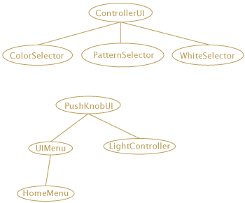
Figure 6 - UI Class Hierarchy
The menus descend from the UIMenu class, which implements all the screen activity and selection. When the KnobPushed method is called, the menu subclass acts upon the current selection.
The three screens that actually set the light patterns are managed by the LightController class. This class has three possible controllers, one for Patterns, another for Colors, and a third for White (brightness). These all descend from the ControllerUI base class. When the home menu selects one of these, the LightController sets an active Controller, and routes all of the activity (knob movement, turning the lights on or off, etc.) through the active controller.
These user interface classes are interrupt-driven; they are invoked by GPIO interrupts when the knob is turned or the button is pushed. Simply instantiating the HomeMenu in main() is sufficient to activate them. The light and motion sensors, however, are polled in a loop at the end of main(). These call into the HomeMenu if they detect the lights should be turned off or back on.
Pattern Files
Pattern files are used to store various patterns displayed on the lights. These are downloaded to the on-board storage via USB, or placed on the SD Card (files on the mbed storage are moved onto the SD Card at system reset).
Since the CuriLights support a nine bit color specification (three bits each for red, green and blue), a convenient shorthand for representing light colors is a three digit number, where the first (hundreds) digit represents red, the second (tens) digit represents green, and the last digit represents blue. Pattern files are simply lists of these numbers, one per line, for each of the lights. If the pattern has fewer lines than there are lights, the pattern is simply repeated for the rest of the lights. For example, to have string of red, white and blue lights, the pattern file contains:
700
777
007
As a tool for creating more intricate patterns, a script was written to convert PNG image files into pattern files. This allows you to use tools like Photoshop as a pattern editor, by creating one-pixel high images.
Most of the above is taken from a design document, posted on the project's web site.
LICENSES
The project is based on the mbed development tools and libraries. This mbed SDK is open source and made available under the Apache 2.0 license