 Josh
JoshProject Requirements
In order to develop an open standard, a set of requirements must be developed to ensure compatibility of Modules, and prevent scope creep.
Requirements can be found on this project's git wiki:
https://github.com/Smerfj/OSAEP/wiki/System-Requirements
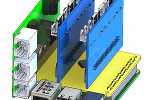
System Architecture
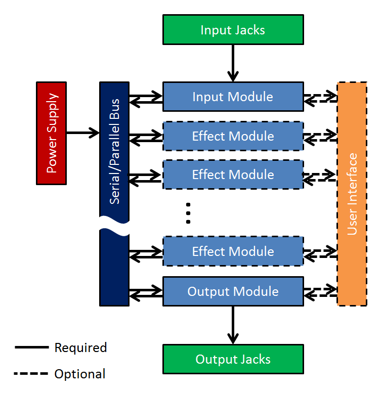
Physical Architecture
Guitar pedal hardware and physical enclosure architecture brings an interesting design challenge: How do you standardize art? One of the biggest draws to creating your own pedal is making it unique. After researching hundreds of pedals, the conclusion is that the hardware architecture must not limit the external configuration. The internal configuration, however, must be specified and standardized.
Link to specification coming soon! (it'll probably also be on the git...)
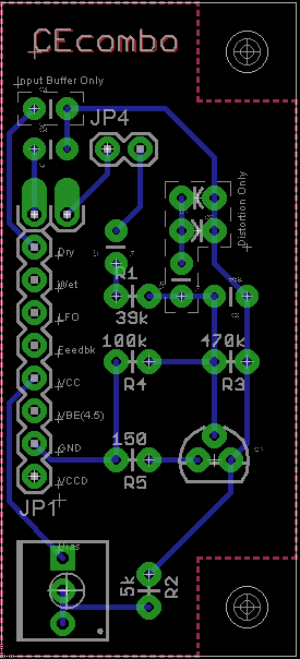
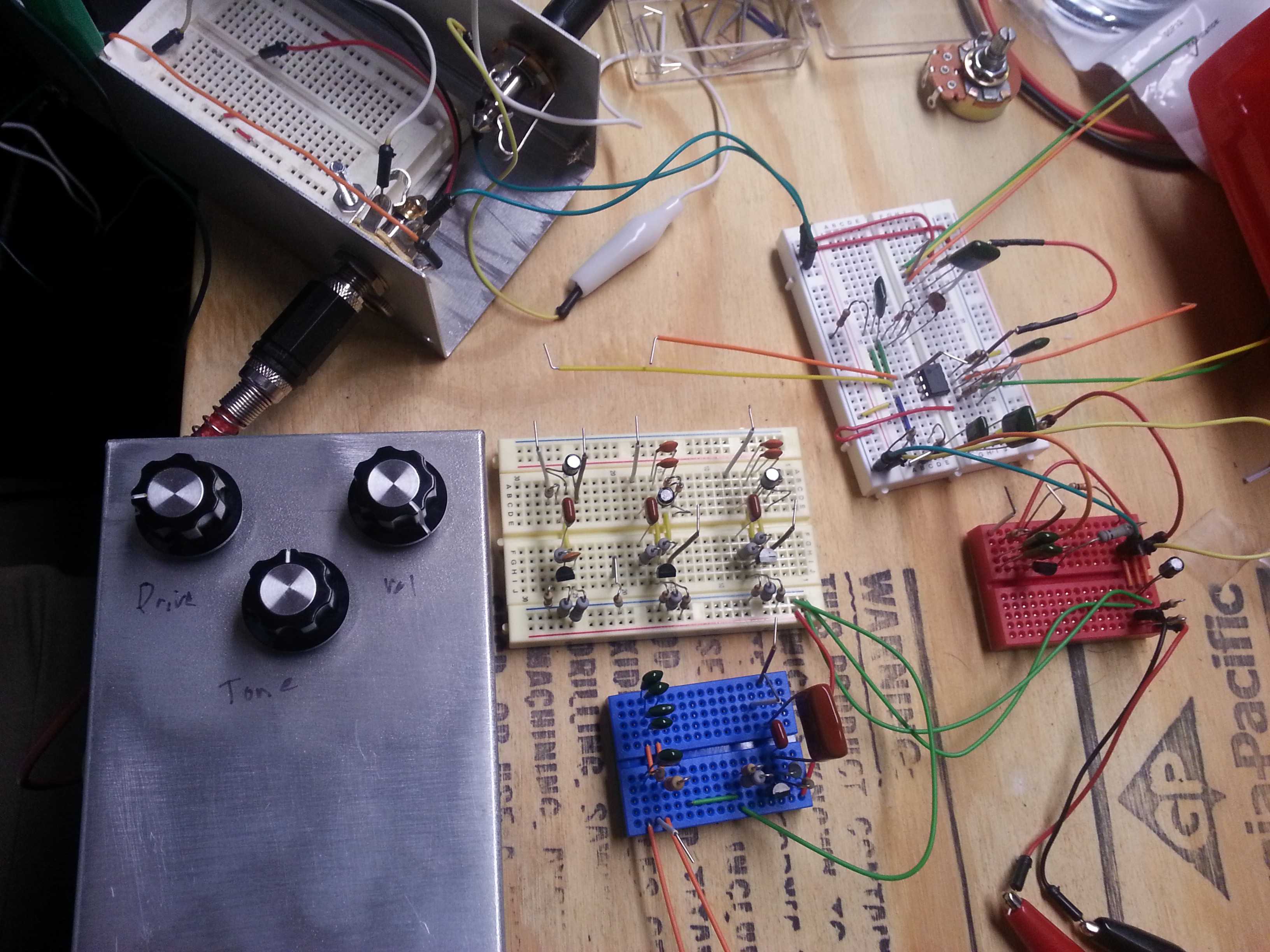
Prototype Status
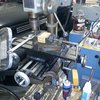
Electronic Proof of Concept:
- POC Intro - Tube Screamer and Big Muff Pi clones
- Modular Tube Screamer clone
- Modular Big Muff Pi clone
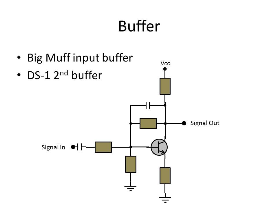
- Tube Screamer Buffer & Drive modules into Pi's Tone & output
- Pi's Buffer & Drive modules into Tube Screamer Tone & output
- TS Buffer--TS Drive--Pi Drive--Pi Tone--Pi output (insane)
Source
Pick up all of the project files as they are released at the git:


 Jon Buford
 Tinfoil_Haberdashery
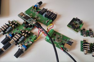
 Michele Perla
 kelu124
Great research! Very useful to anyone building their own pedal.