 Josh
JoshA quick update... after looking at how much work it would be to assemble even a small batch of perf-board prototypes, it seems like a better idea to go ahead and design some circuit boards and have them made at a board house. So the past few months in my spare time (which isn't much) I have been learning Eagle and attempting to design some boards. I have several designs, including the buffer and drive sections of the Pi and the TS buffer circuits that I used in the POC. After a few iterations of the Pi circuits, I realized that there are common enough features that I can design a single board to handle both the buffer and drive by either including or excluding components. This is great news, as it means I can get a batch of these and choose the function when the components are soldered on. I still have some things to add, such as the OS licensing marking and Project name, but here's the first rough schematic:
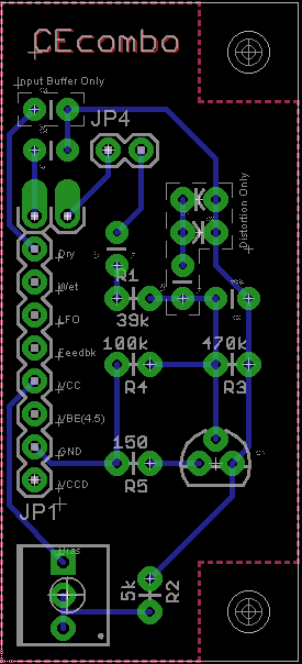
I'll post another update when I get some more boards routed and make an order.
Discussions
Become a Hackaday.io Member
Create an account to leave a comment. Already have an account? Log In.