When one needs to change a connector for a rechargeable battery, he/she will connect the red wire from the battery to the red wire of the connector, right?
The same goes to the black wire, right?
I was sure too until I learned this could be wrong by means of active learning.
I must admit I have never used Li-ion polymer (LiPo) batteries before because 5V powerbanks were good enough for my portable projects. This time the size of a bank and the need for a cable called for using a bare battery instead. I happened to have two batteries shown with a LiPo charger below
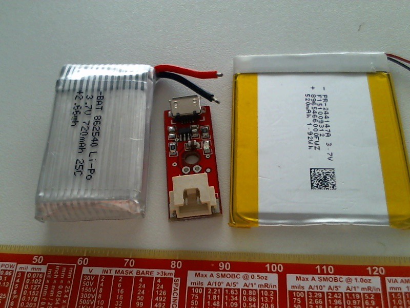
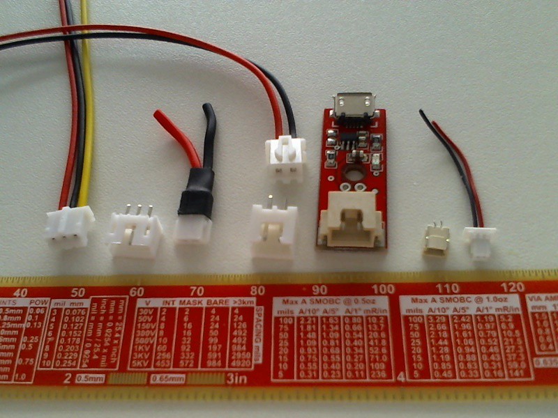
that came a while ago (before some overdensied batteries started catching fire) as parts of some kits. Sparkfun and Adafruit websites provided all the information I required about these. The battery on the left does not feature built in overdischarge protection circuitry but can source substancial currrent (25C on the label means up to 25*720mA). It is commonly used for radio controlled (RC) models where the user is reponsible to switch the battery off on time when its voltage drops close to 3V. The battery on the right is equiiped with this protection, which adds expense but allows for unattended operation. Unfortunately both batteries and the charger came with JST (name of the company developed self-locking connectors withstanding vibration well) connectors of different spacing (shown below with mating connectors, respectively 2.0, 2.54 and 1.0 mm connectors from left to right)
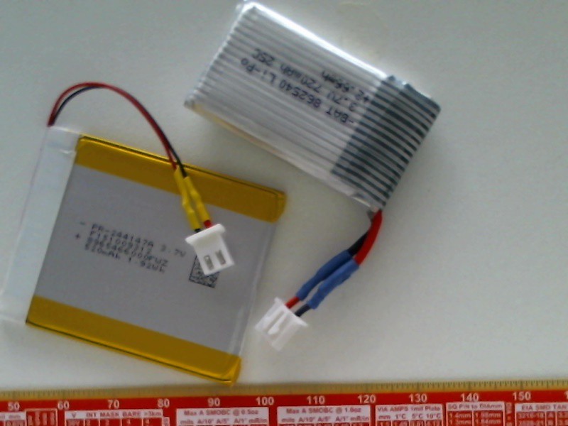
Interestingly, both batteries not only came charged but also retained quite a bit of charge after being stored for a few years. This was discovered without using any instruments. When I cut off the bigger connector in one go I shorted the battery with the cutter and wires started burning straight on (not very surprising for a rated 15 A max current). As it happened, even after this short the battery retained over 4 V on its terminals. The other connector was cut off one wire at a time then.
When I started soldering battery wires to the 2.54 connector, I recalled a recently viewed video regarding a story which started when rechargeable batteries were connected to a power supply in a wrong way. Of course this would not happen to me as I connected red (positive terminal) to red and black (ground terminal) to black. For this reason I just plugged the battery into the shield. More smoke followed, now from the battery shield. After disconnecting things I found that color marking of wires on the batteries I had and 2.54 connectors was exactly opposite to each other. The battery still retained over 4V thus was ready for even more damage. (I recall a university friend whose project eventually turned into what he finally named 'a device for destroying transistors' despite this was not the original purpose. No doubts this LiPo battery could be used to power the device without the mains adapter making it possible destroying transistors anywhere in the field.)
This way of learning things is called active learning - since I even make sure that the wires are not covered with the heat shrink tube not to forget to check the polarity before connecting the batteries to any new board
Inspection of the battery shield showed that the TP4056 integrated LiPo charger reacted to the abuse by releasing its magic smoke (note 1)

Some people say that a fool learns from his own mistakes and a wise man learns from mistakes of the others. As only wise people read this log, I will refer to and discuss some protection options:
- electroBOOM video (protection of a power supply from attaching batteries with reverse polarity using a single diode);
- EEVblog video (detailed analysis of input protecting circuitry for digital multimeters using metal oxide varistors (MOV) and quick blow fuses);
- the purpose of the series resistors for the ADC module. As it happens, most if not all integrated circuits have two diodes internally connected to every input pin to protect it from electrostatic discharge. This used to be a very common cause for destroying semiconductor components; here there is a schematic diagram and discussion for this sort of protection. Adding a resistor in series makes hese diodes working as a voltage clamp. The datasheet of the ADC chip from the ADC module states that these diodes can withstand 10 mA of continuous current. With the series resistance of 10 kOhm one would expect the module not to be damaged even if the resistor is connnected to say, a 50 V source with decent safety margin. Without this resistance such a connection would increase the amount of magic smoke in the wild.
The module will be unable to measure any voltage beyond the one of its power supply but this can easily be fixed with a potential divider.
The downside of using the series resistor is that it makes some potential divider with the input impedance of the pin as well, understating the measured voltage compared to the actual value. As the input resistance of the ADC channels exceeds 3 MOhms according to its datasheet, this understatement will be around 0.3% which seems acceptable to my needs. If the need for more accurate measurement arises later, each channel of the voltmeter should be compared against known (or measured with high accuracy and resolution) voltage. The actual to measured voltage ratio can be used to multiply the measured values later.
Finally, I have a few TP4056-based boards on order and hope that I will be able to replace the burnt one on the Wemos mini shield mitigating damage caused by active learning this time.
Discussions
Become a Hackaday.io Member
Create an account to leave a comment. Already have an account? Log In.