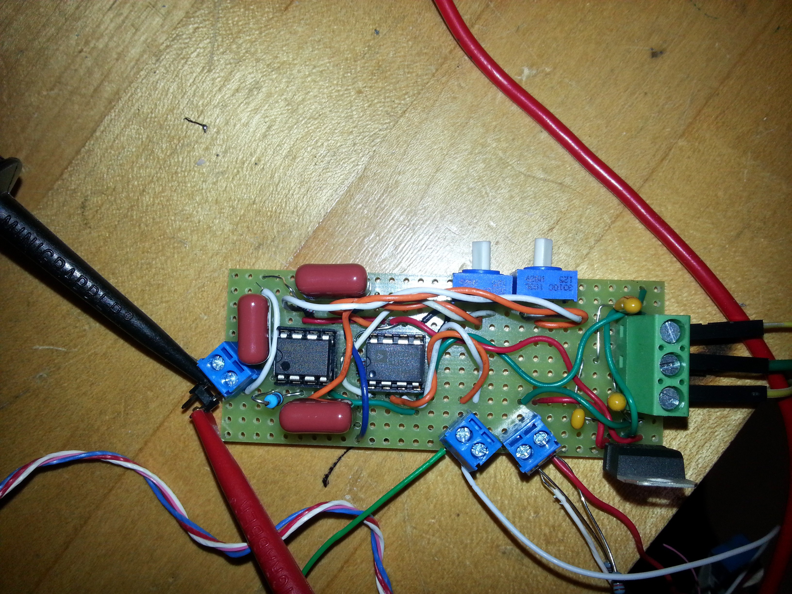
Strain gage amplifier/conditioner:
The Rev1 amplifier/conditioner circuit was built and tested on both the initial single strain gage test bar, and the fully instrumented crank arm (pictured). The results were very promising, as a gain of approximately 2,500 was used, and the pk-pk fluctuation of the signal was <15mV. Not inconsequential, but in regards to the instrumented crank arm, this amounts to an error of 3lbs (+/- 1.5lbs about mean). The next iteration will move towards a single-side supply, making the circuit much easier to power by a single battery. More importantly, the new revision will provide a 0-5VDC output, with 2.5VDC corresponding to 0% strain. I've abandoned the pursuit to make a device that does not rely on a microcontroller to communicate between the analog-to-digital converter (ADC) and the bluetooth transceiver. Since doing this, it makes component selection much easier, and permits the application of digital signal processing, utilizing a built in ADC, and ability to expand features (scope creep?). The 0-5VDC output signal from the strain gage amplifier/conditioner will be compatible with the microcontroller ADC.
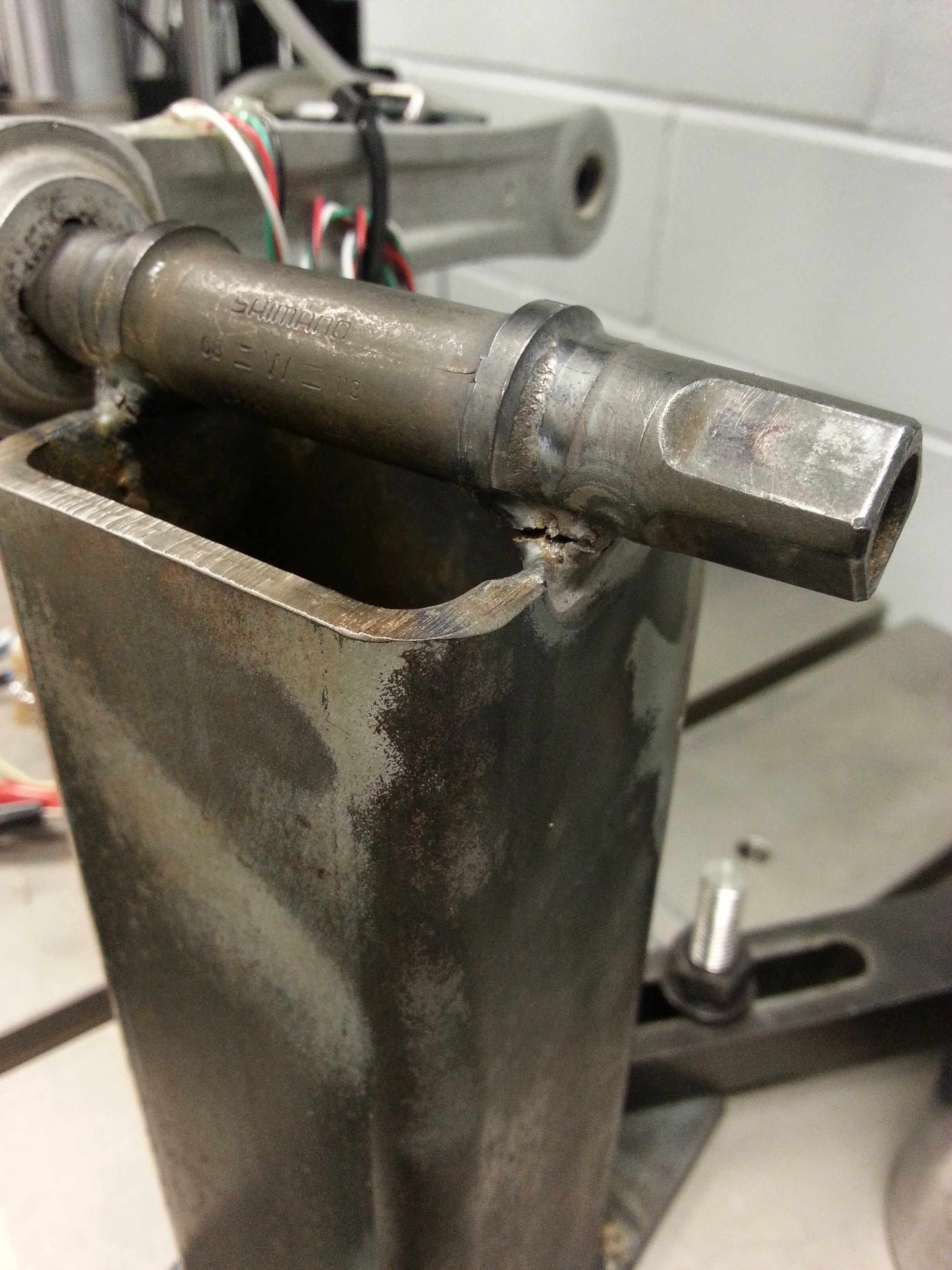
Instrumenting the crank arm:
This was much easier than I expected. I had two cranks to instrument, and intentionally instrumented one haphazardly. Ironically, I accidentally tore the leads off of not one, but two strain gages on the one that I spent a lot of time on. However, the 'haphazard' crank worked beautifully. I built a special fixture to allow calibration, and fatigue testing of the strain gages, but sadly I was only able to run one loading run before my welds broke. That is why the applied load curve is non-linear.
I used the same epoxy specified in my previous project log, and it appears to be working, yet I won't know for sure until a proper fatigue test is done (1 million cycles or more).
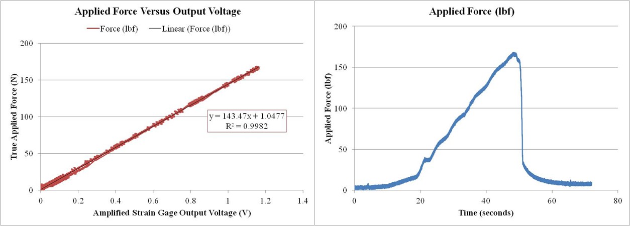
Initial calibration:
As previously mentioned, the strain gages were placed 'haphazardly', in that the strain orientation was not aligned along the long axis of the crank arm as well as it could have been. Regardless, the linearity was much better than expected, and the hysteresis was not significant enough to measure (see graph). The error was also independent of the applied load, and fluctuated +/-1.5lbf. This meets my design requirement, but more testing is needed to confirm the result. Due to the premature failure of the calibration fixture, a proper calibration could not be completed (yet).
Another much needed test is to measure the amount of instrument crosstalk. The placement of the gages was designed to measure the applied bending moment and be insensitive to forces applied along the long axis of the crank arm. In essence, if a person is resting on the pedal with the crank resting at bottom-dead-center, there should be no output. Along with the aforementioned fatigue test and hysteresis test, measuring crosstalk will need to be completed before moving forward.
Path forward:
Order components for Rev2 amplifier/conditioner
Build Rev2 amplifier/conditioner
Re-weld test fixture
Repeat calibration tests
Discussions
Become a Hackaday.io Member
Create an account to leave a comment. Already have an account? Log In.