The strain gages arrived, and initially seem to be okay based on how much the resistance varies from sensor to sensor. The difference ranged from 0.0 ohm to 0.7 ohm, which appear to be on par with more expensive sensors. It doesn't tell the whole story, but so far so good.
I was researching glue and decided on a high strength (3.5ksi, 24MPa) epoxy I purchased from a home improvement store. I followed some tutorials I found on both Vishay's and Omega Engineering's website as well as on YouTube. After preparing the surface with acetone (to degrease) and isopropyl alcohol (to remove acetone residue), I adhered the strain gage using the tape method and left the epoxy to cure for 24hrs. I then soldered on leads and gave it a shot (see photo).
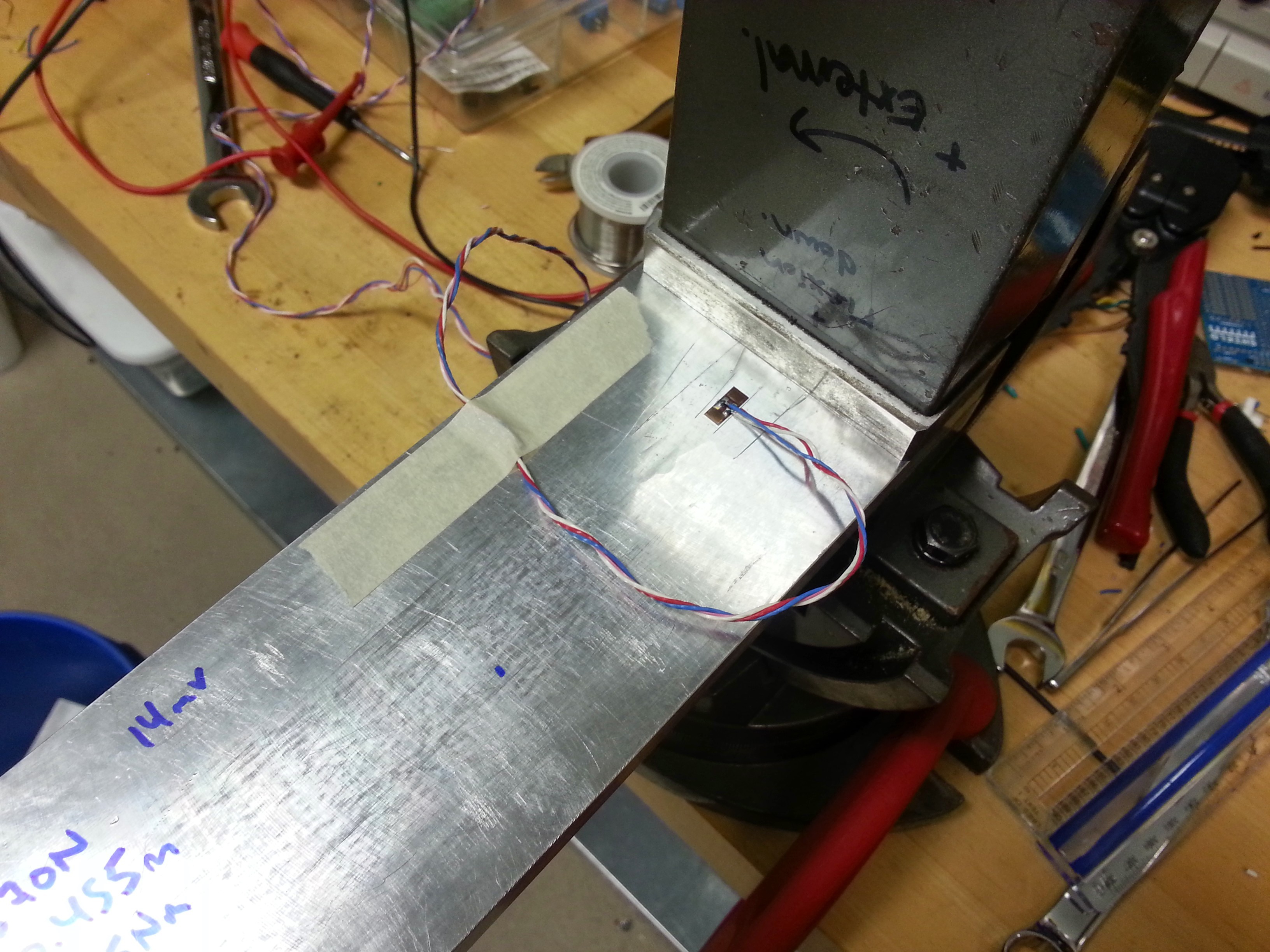
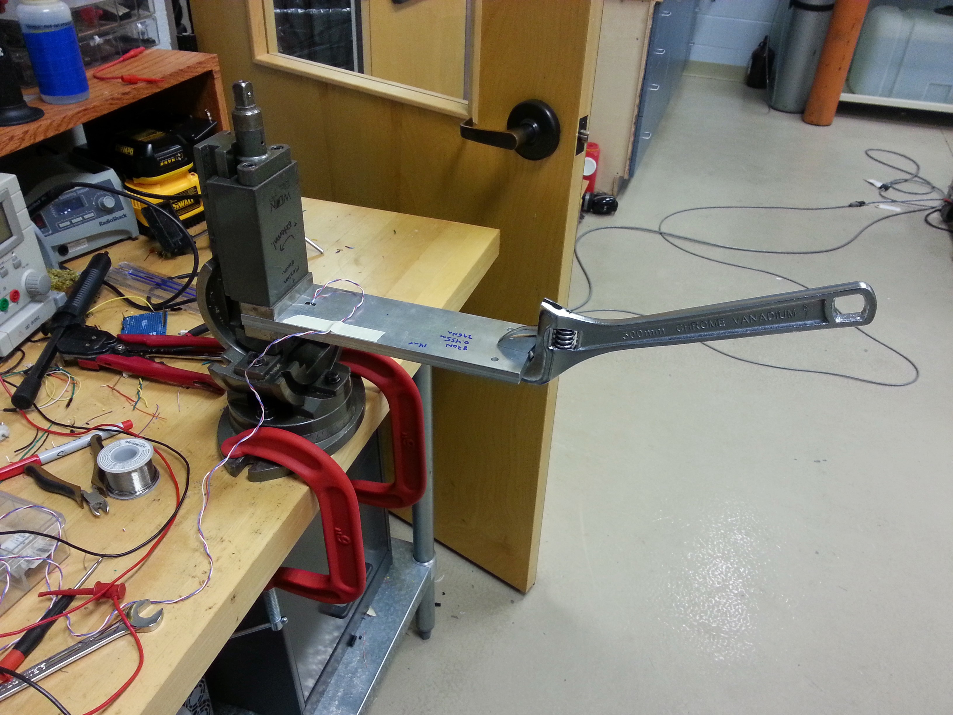
With a variable resistor set to match the resistance of the strain gage, I was able to make a voltage divider with a 10VDC power supply. With approximately 350Nm of bending moment on the beam (see photo), I was able to get a output voltage change of 14mV. Based on this, I estimate that a full bridge will provide ~52mV in practice.
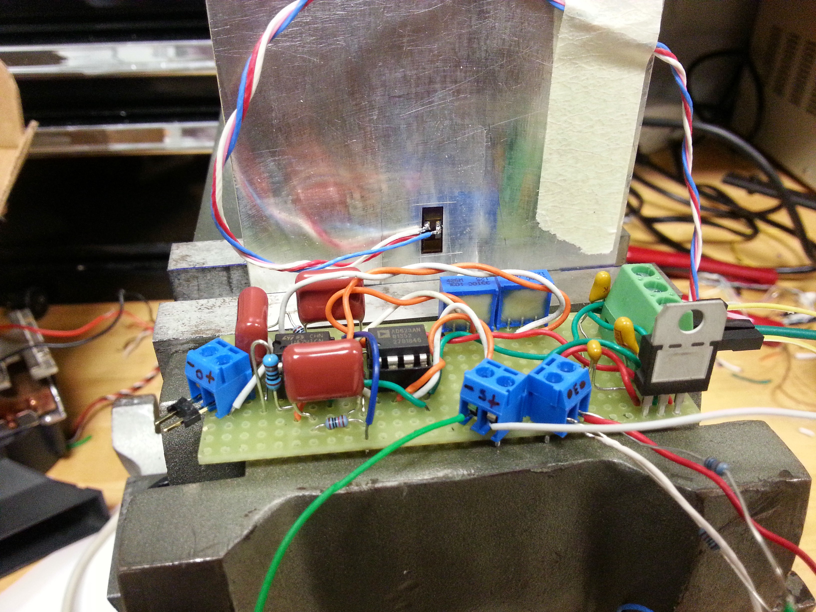
I designed the first version of the amplifier/conditioner (see photo). It consists of an Analog Devices instrumentation amplifier combined with an active 3rd-order Butterworth filter. There will be a lot of differences between this initial design and the final version, but this will be enough to hash out appropriate gains, noise suppression techniques, and measure the linearity and calibration values of an instrumented crank once it is created (soon). All of the parts have been acquired, so the first version will be made with a standard perf board this week, and hopefully noise levels will be below 2mv pk-pk else a custom PCB will replace the perf. Hopefully it doesn't come to that just yet.
Discussions
Become a Hackaday.io Member
Create an account to leave a comment. Already have an account? Log In.