 Thomas Van den Dries
SmartSupply is a digital battery powered lab powersupply. It is Arduino compatible and can be controlled via PC over USB. It is completely open source, all files can be found on my GitHub!
I also created an Instructable with step by step instructions. I hope you like it!
Specifications:
- 0 - 1A, steps of 1 mA (10 bit DAC)
- 0 - 20V, steps of 20 mV (10 bit DAC) (true 0V operation)
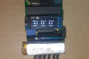
- Voltage measurement: 20 mV resolution (10 bit ADC)
- Current measurement:
< 40mA: 10uA resolution (ina219)
< 80mA: 20uA resolution (ina219)
< 160mA: 40uA resolution (ina219)
< 320mA: 80uA resolution (ina219)
> 320mA: 1mA resolution (10 bit ADC)
Features:
- Constant voltage and constant current modes
- Uses a low noise linear regulator, preceded by a tracking preregulator to minimize power dissipation
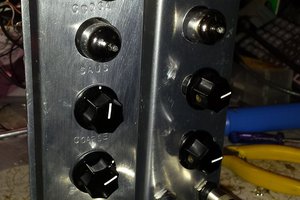
- Aluminium case end panel used as heatsink
- Use of handsolderable components to keep the project accessible
- Powered by ATMEGA328P, programmed with Arduino IDE
- PC communication via Java application over micro usb
- Powered by 2 protected 18650 Lithium Ion cells
- 18 mm spaced banana plugs for compatibility with BNC adapters
Theory of operation:
To understand the operation of the circuit, we will have to look at the schematic. I divided it into functional blocks, such that it is easier to understand; I will thus also explain the operation step by step.
Main block
The operation is based around the LT3080 chip: it's a linear voltage regulator, which can step down voltages, based on a control signal. This control signal will be generated by a microcontroller; how this is done, will be explained in detail later.
Voltage setting
The circuitry around the LT3080 generates the appropriate control signals. First, we will take a look at how the voltage is set. The voltage setting from the microcontroller is a PWM signal (PWM_Vset), which is filtered by a lowpass filter (C9 & R26). This produces an analog voltage - between 0 and 5 V - proportional to the wanted output voltage. Since our output range is 0 - 20 V, we will have to amplify this signal with a factor of 4. This is done by the non inverting opamp configuration of U3C. The gain to the set pin is determined by R23//R24//R25 and R34. These resistors are 0.1% tolerant, to minimize errors. R39 and R36 don't matter here, as they are part of the feedback loop.
Current setting
This set pin can also be used for the second setting: current mode. We want to measure the current draw, and turn the output off when this exceeds the wanted current. Therefore, we start again by a PWM signal (PWM_Iset), generated by the microcontroller, which is now lowpass filtered and attenuated to go from a 0 - 5 V range to a 0 - 2 V range. This voltage is now compared to the voltage drop across the current sense resistor (ADC_Iout, see below) by the comparator configuration of opamp U3D. If the current is too high, this will turn on an led, and also pull the set line of the LT3080 to ground (via Q2), thus turning off the output.
The measurement of the current, and the generation of the signal ADC_Iout is done as follows. The output current flows through resistors R7 - R16. These total 1 ohm; the reason for not using 1R in the first place is twofold: 1 resistor would need to have a higher power rating (it needs to dissipate at least 1 W), and by using 10 1% resistors in parallel, we get a higher precision than with a single 1 % resistor. A good video about why this works can be found here: https://www.youtube.com/watch?v=1WAhTdWErrU&t=1s When current flows through these resistors, it creates a voltage drop, which we can measure, and it is placed before the LT3080, since the voltage drop across it should not influence the output voltage. The voltage drop is measured with a differential amplifier (U3B) with a gain of 2. This results in a voltage range of 0 - 2 V (more on that later), hence the voltage divider at the PWM signal of the current. The buffer (U3A) is there to make sure that the current flowing into resistors R21, R32 and R33 is not going through the current sense resistor,...
Read more »

 Dr.Stone
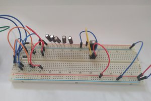
 256byteram
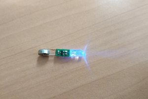
 Pnoxi
Pnoxi
This looks great, I think I'll make one myself. What is the transient response and output ripple like?
Did you have any issues with the lt3080? I know Dave Jones of the EEVBlog put his power supply project on hold due to an issue I believe with the set voltage burning out the chip under some conditions.