Close
0%
0%

Intervalo-Thingy

ATMEGA 328 based intervalometer. Stupidly complicated for what it does. This is now its official name.

Similar projects worth following
Intervalometer for DSLR cameras that use a 2.5 mm audio jack for wired remotes. Based off of the ATMEGA 328P. Designed with a Canon EOS Rebel T3i as test camera. Coded using arduino IDE.

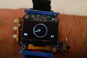
This project was originally supposed to use a rotary encoder for input, but the library I used kept spitting out garbage and I decided to use tactile switches instead. These were much more difficult to implement than I expected, but they now work well enough for my purposes.

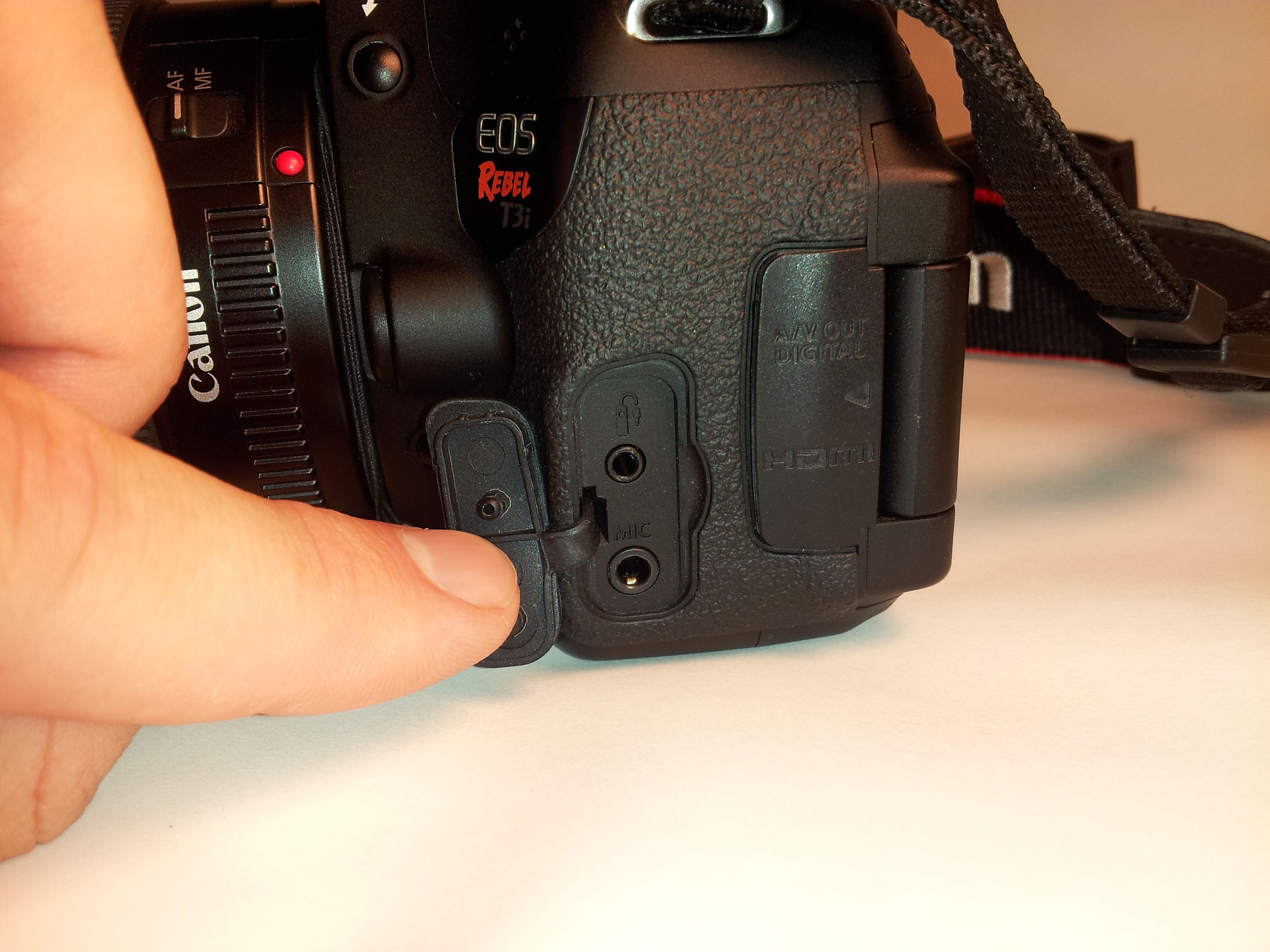
After completing my first project (blinky LEDs), I decided that I would like to make something much more complicated. I have a Canon EOS Rebel T3i DSLR and thought it would be interesting to make something that would increase my photography toolbox. Hence this project. Apologies, I don't have any photos of the previous iterations and there were a few.

This project could be much more complicated than it is, admittedly. I am toying with the idea of adding a RTC chip so I can add an alarm function (have it start at a set time). It would be pretty awesome to be able to set a goal number of exposures. I am also toying with adding a solar panel (which I already possess).

This build log thingy is kind of funny. Hopefully I can break up my progress into sections that make sense.

An intervalometer is a device used to control the photo interval for time-lapse photography. They are super cheap to buy commercially. I saw a few on amazon for less than 15$. My device will also be able hold the shutter open for long periods which means it can be used for astrophotography or for light painting. Eventually I would like to add stepper control to make it possible to do side-scrolling time-lapse videos (with help of a track).

INTERVALOTHINGY SVG.zip

If you wanted to etch them yourself. The schematic has all the parts and values.

x-zip-compressed - 49.77 kB - 03/15/2016 at 01:00

Download

Adobe Portable Document Format - 61.77 kB - 03/15/2016 at 01:00

Preview
Download

Intervalothingy_v1.ino

The code. You'll need the liquid crystal library to make it work.

plain - 10.43 kB - 03/14/2016 at 23:47

Download

View all 14 components

  • Mostly Done

    The Feature Creep03/14/2016 at 23:24 0 comments

    So, I've actually finished this project more or less.

    I used a dual channel optoisolator to fully segregate the mcu and camera electricals. Got a board etched. Killed the battery controller and simultaneously learned that making all the boards separable is nice and will be a design objective going forward. Bought a boost converter for AA batteries and installed it. Battery life is really, really long. I got mad at the tupperware enclosure and moved it into a cardboard box that sparkfun shipped me something in. Next I need to put a thick red filter on the lcd so I won't accidentally wash out my photos when I want to peek at the status while doing astrophotography. And maybe a grey one too. Dim and red is the goal at night.

    So far it works pretty well. There are some things I want to improve, but I mostly did this project to advance my electronicals knowledge. The el-cheapo LCD I'm using has some quirks that I had to code around.

    I guess I'll explain. The LCD is the wrong color. It's too bright. The backlight isn't an LED one. I wanted to use pwm and a transistor to control the brightness, but that doesn't work on this backlight. The details about it were pretty sparse when I bought it. It refreshes slow. Really slow. At first my code blanked the screen every five times through the loop as my method of getting rid of unwanted characters when we went from 3 digit numbers down to 2 digit ones. This was giving me headaches with all the flickering. I also tried this method on a nicer LCD that I henceforth killed. Worked ok there, but on this one it was terrible.

    I got around this by only overwriting the characters when they change. Most of the display never gets blanked (unless switching the mode) which makes it a lot easier to look at. No flicker at all.

    If I could do this over I would probably get one that is red on black with an led backlight. I still like the method of only overwriting characters that change instead of blanking the whole thing. It took a little more work but turned out better. And don't solder the LCD on permanently. Make it removable!

    I'll get some pictures of it in its newest home posted. I'll throw my code up as well, if anyone is interested.

  • DONE (maybe)

    The Feature Creep12/29/2014 at 06:34 0 comments

    So it has been a while since I updated this. And no, I haven't forgotten it.

    I got the Dragon to upload the chip just fine, it went perfectly. Apparently I had it hooked up wrong. Once my brother looked at it he immediately got it to work. Glad to have him around.

    Anyway, I went back through my code and got all of the major bugs fixed. I refrained from adding a solar panel or an RTC. I got my board laid out in Kicad, etched, soldered, and installed in a tupperware dish. It works perfectly! And it is my first double sided board too!

    I went down to the environs of Cabo San Lucas and did a few astro-photography exposures. I'll throw them in the photos section on the front page of this thingy. You will notice a few of the pictures have an orange glow on one edge. This was due to the orange status LED I had hooked up at the time for debugging it. I have since removed it. I hope to go do some more exposures soon, but the cloud cover has been pretty heavy lately. As for testing the time-lapse functionality I need to go find a good place to do a test run. I'm thinking of keeping it simple and doing a sunset. A really cloudy day could be interesting to see the clouds race by. I'll try to do that later this week.

    Annnd done!

    Also, I did a test run of the battery life with my existing setup. It recorded over 8k exposures at the last time I checked before it ran out of juice. It would have been smart to have added a battery gauge. I'll do that with my next project. I don't foresee any problems with battery life as it stands. The camera will run out way before the Intervalo-thingy.

  • Fight The Creep

    The Feature Creep10/07/2014 at 23:31 0 comments

    I can't seem to get the AVR Dragon to see my 328p. It always tells me that the voltage is off what it expects, but I am using external power (and it is well within the voltage range). So I'm stumped. I think that I will have to end up using the Arduino as the ISP again. I already got that to work when I uploaded the bootloader. And yes I am aware that I am entirely a noob. Triple checked the pinout, verified the voltage, still not talking. I'll go back to what I know works. My instinct says its the Dragon, and I've got no money to replace it now anyway. My other guess is that I fried my ATMEGA's. Learning experiences don't have to be expensive to hurt. I'm hoping that isn't the problem.

    The datasheet for the RTC tells me that the crystal will not oscillate if the ground plane is not run under the pins for the crystal. I'm guessing it is a noise issue? So I need to either protoboard it or spin a couple of little breakout boards. And I am leaning more toward spinning a couple of boards for it. I eventually want to make a desk clock out of a VFD I got from Noritake-Itron and would like to use the other RTC I bought (and I really want someone to make a module so I can easily use WWVB for a stupidly accurate clock).

    Strangely, I am looking forward to coding for the RTC. I have to learn how to use I2C and it will be my first time using the interrupt pins. It will require a lot of rewriting the timing functions as well, which taught me a HUGE amount the first time through. The alarm feature of the DS1337 should make it so I could use the sleep function in the Arduino in between the shutter events which would be a huge boost for the battery life. I've also decided the solar panel is overkill. The only big (ish) current drain is the LCD and I have it written to turn off the backlight ten seconds after the last button press. Upon reflection it would be nice if the first button press only turned on the backlight and didn't count for anything else. And the strategy is coming to me as I think about it...

  • Going without the arduino

    The Feature Creep08/08/2014 at 11:51 0 comments

    Building a box to house your crazy bundle of wires and arduino and the other stuff is kind of annoying. I know this because I did it. It was as heavy as a brick and made entirely by hand (hacksaw, drill, and files). It was made of aluminum and black acrylic and it was stupidly heavy. It weighed more than my camera before I put all the batteries in. Also, it used AA batteries. Next time it is going into a tupperware dish. Seriously.

    The move from the breadboard to the case killed my project dead. I have a terrible hobbyist soldering iron and the skills to match. I think I got that LCD too hot when I resoldered it with longer leads. Dead. Since then replaced with a better one. Not so dark. Its all contrasty.

    My Arduino cost around twenty bucks. The chip and crystal cost around three bucks. So I decided to ditch the Arduino (i.e. free-up) and write the chip using my Arduino as an ISP. Then I decided that I wanted to avoid removing the atmega every time I needed to upload the code. I then wired it for the Adafruit ftdi cable. Which only worked once. After grinding my head on the floor I learned that you need to have it use the reset pin on the atmega before it will upload. That cable does not have that pin and I couldn't find any instructions on how to interface with the pin it does have, which is probably the same function. It wasn't shown in the datasheet. Growl. I want that magic smoke to stay in there. I'm too new to try things.

    I now faced a dilemma in how to upload my sketches? And now we are up to the present. I now have borrowed a AVR Dragon and am using Atmel Studios instead of the Arduino program. I need to research if I can use the MOSI and MISO pins for multiple purposes. Right now they are interfacing with buttons. I have an idea on how to consolidate those to fewer pins as well. My thinking goes, if I read the pin using analogRead instead of digitalRead I should be able to differentiate between them if I use differently valued resistors as pull ups. They would give different values which would be super easy to code for. Any problems I'm not seeing? I'd appreciate any comments.

  • Interfacing with a camera

    The Feature Creep08/08/2014 at 11:28 0 comments

    The next order of business was to successfully tell the camera to actually take a picture. Certain Canon cameras use an interface for wired remotes that is simply a stereo 2.5mm cable. All you have to do is close the correct line to ground. One tells it to focus and the other to shutter. It has to be held for about a second to take the picture. This was easier than anticipated. One interesting difficulty is that I had a hardish time finding a 2.5mm jack for my controller end of the project and it was hard to find a decently long cable. I did find a 3.5mm to 2.5mm cable that is what I have ultimately used. By the way, I don't like my 3.5mm jack. It is hard to push in the connector and is easy to pull out.

    The remote port

    The upper hole is the one we want.

    To pull that line to ground I used NPN transistors as switches and included a third one to control the LCD backlight with PWM. I am considering using an optoisolator to have complete isolation between the devices. After tuning the length of the pullup I had a working setup! I was successfully getting the shutter to close every time. However I also learned the drawbacks of using delay() in your code as it shut the whole thing down, in essence, with all the waiting.

    This tutorial (http://arduino.cc/en/Tutorial/BlinkWithoutDelay) helped me to find the way around this. I started using the millis function as my clock and again got the camera to successfully focus and shutter at the important interval. Better yet, because it bases the timing off of uptime it also made it so my brief delay to debounce the button presses doesn't affect the interval between shutter events. I am considering, as previously mentioned, that I could use an RTC chip to set my intervals and add an alarm function to start the time-lapse photo taking. However, I am running out of pins...

  • LCD troubles

    The Feature Creep08/08/2014 at 11:02 0 comments

    Something I didn't expect was how easy the LCD was to interface. Once it was hooked up correctly it was super easy to code for. The liquid crystal library worked great for this. Going forward I now know it would be wise to get serial connection LCDs instead of the parallel one I am using. The library supports them and it takes a lot fewer pins. Best yet would be I2C. One problem I did have was ghost letters left over after transitioning from three digit numbers to two digit ones. Apparently the chip on the LCD didn't automatically do this (stupid this didn't occur to me before). So I set up a loop cycle counter that would increment up every time it passed through the loop. I told it to clear the LCD every fifth pass and this fixed the problem. There was a little jitter visible, so I tuned the number until it disappeared. The LCD now worked perfectly.

  • Buttons are hard

    The Feature Creep08/08/2014 at 10:51 0 comments

    So, the next thing I obviously needed was to come up with a easier and more reliable source of input to my project and I decided on tactile switches. I actually harvested a couple from old computer case power buttons for my initial tests. After hours of looking for a good coding strategy I came upon the state change counter tutorial which with modification (duh) paved the way for me (http://arduino.cc/en/Tutorial/ButtonStateChange). However, I was still getting a lot of garbage input from each button press. I needed debouncing. After familiarizing myself with it at the most simple level I modified the code to use a simple delay after each press. It is very short and should have no real impact on the interval between photos. Now I have buttons that show each press accurately (if you aren't too fast on the press). I may revise this later and find a method without using delay. I would also like to make them increment in fast forward when the button is held down. And while writing this a strategy is forming...

  • Tinkering with rotational controlling

    The Feature Creep08/08/2014 at 10:39 0 comments

    The very first thing I did was to obtain some rotational encoders and hook them up according to instructions off of Arduino including one of their libraries (http://playground.arduino.cc/Main/RotaryEncoders). My particular encoder was very cheap and almost worked. Once every turn or so it would increment the wrong direction. After raising the local ambient profanity levels to the maximum my instruments could endure, I decided this was a stupid waste of my time and unnecessary to the greater goals of the project. They are now waiting for their next opportunity to torment me in their little baggies from mouser. Sometimes I can hear them plotting my downfall when it is really quiet.

View all 8 project logs

Enjoy this project?

Share

Discussions

Arcadia Labs wrote 08/08/2014 at 23:19 point
Hey very cool project !
I did almost the same a few weeks ago, I documented everything on my weblog : http://hardware-libre.fr/2014/06/arduino-fabriquer-un-intervallometre-evolue/
It's in french but you could use the schematics and source code is on on GitHub ;)
I2C LCD is not really needed.

One thing I'll do on mine this week-end (I'll be using it on vacations next week) is adding 2 opto-isolators between the shutter/focus atmega GPIOs and the camera. Way safer.
I'd also like to replace my 2 buttons navigations with a rotary encoder.

Keep going !

  Are you sure? yes | no

The Feature Creep wrote 08/09/2014 at 02:26 point
Thanks. I notice my lcd screen darkens when the shutter events occur and I've wondered if this would fix it. The optoisolators, I mean.

I'll have to check out your project, thanks for the link. And thanks for the comment.

  Are you sure? yes | no

Similar Projects

Does this project spark your interest?

Become a member to follow this project and never miss any updates