 jlbrian7
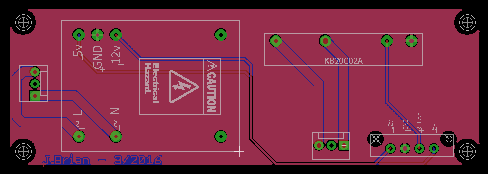
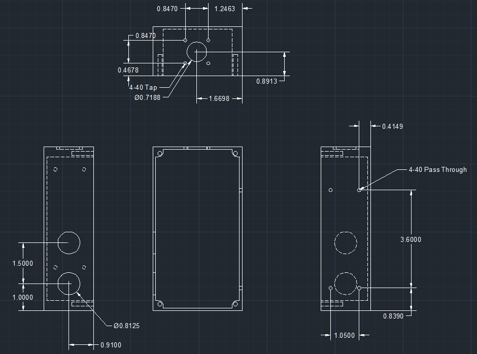
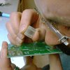
I had made a box to control the metal loop several years ago, and wanted to revisit the project to improve the design and make it more robust.
The project originally started because the use of spring loaded sensing wires was not the best solution, but was what was available. After pricing some of the ultrasonic sensors available for industry (currently between ~$330 -$1400) I thought that I could do better, and if not then one could always be purchased. I built the original loop controller for less than $100. All of the electronics came from radioshack and a local electrical supply store, this way repairs could be made that day instead of waiting for a part. The frame was built from scrap metal.


 Kacper
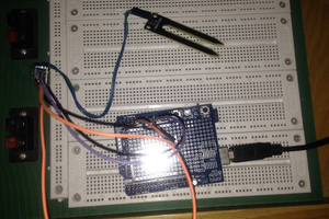
 Andrew
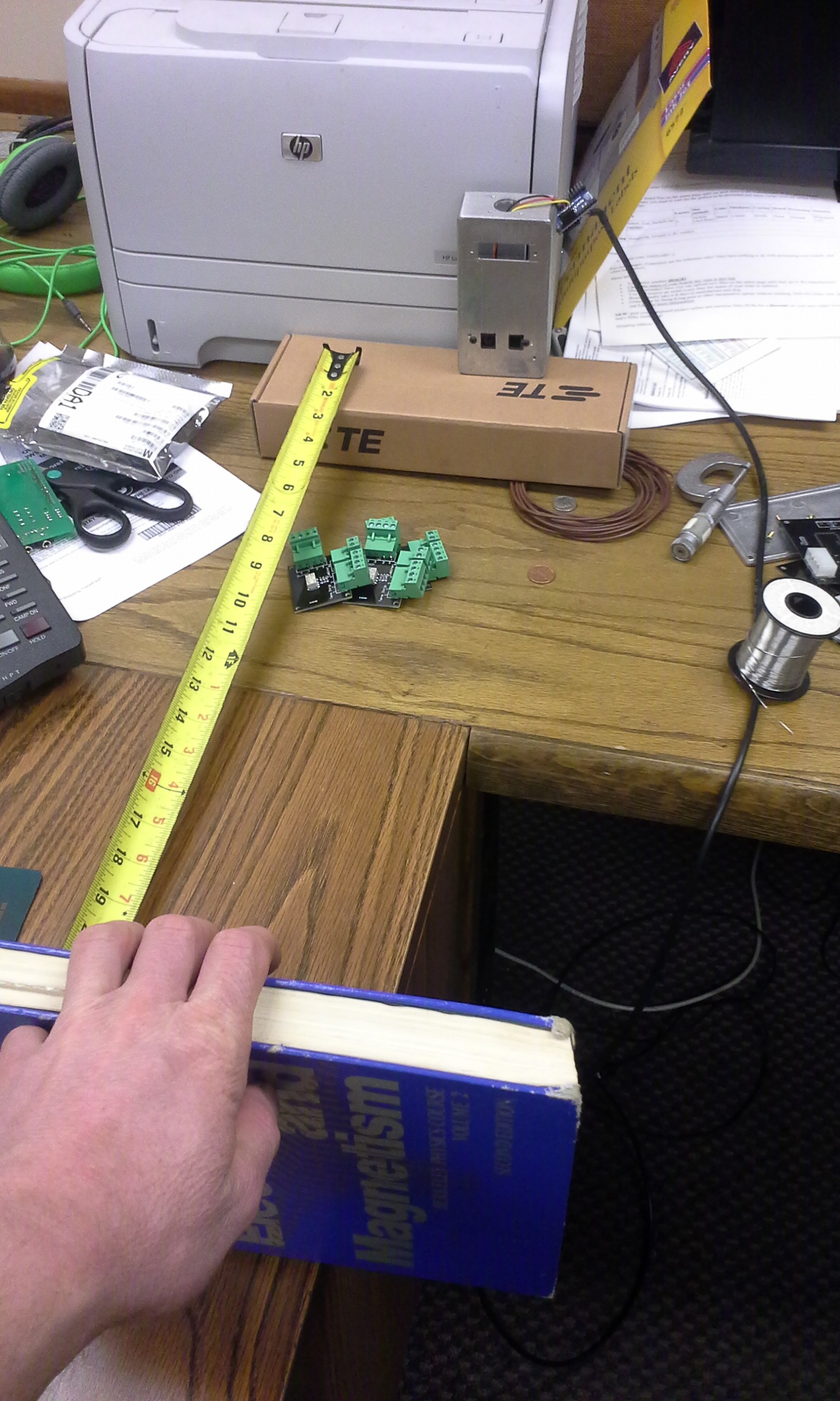
This sounds very interesting.
Can you post some pictures of what's going on? I'm not familiar with this kind of machine and it certainly sounds interesting.