jlbrian7
-
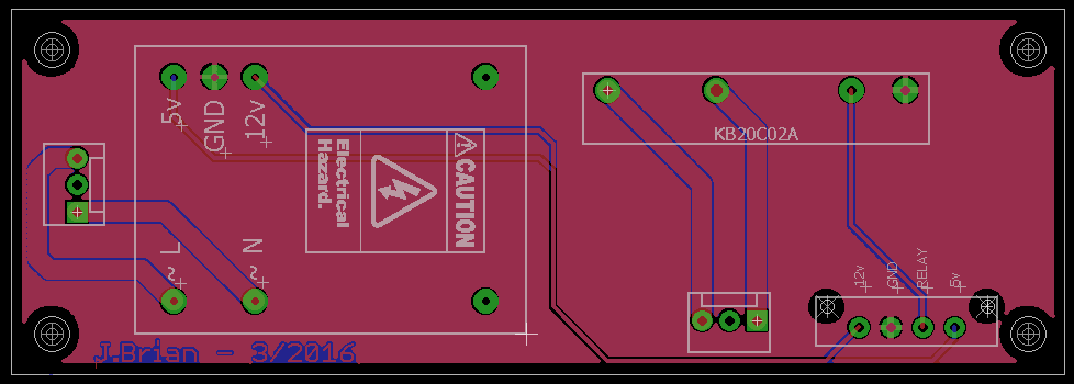
Power Box
03/08/2016 at 20:55 • 0 comments![]()
![]()
-
Note:
02/06/2016 at 14:21 • 0 commentsI tested objects with different colors, but not necessarily different reflectance. I will check the sensor shortly on highly reflective material, and make sure that the curve still fits.
-
Caution
02/05/2016 at 13:19 • 0 commentsThe sensor is very sensitive, and not having the object being detected parallel to the sensor can create a measurement +/- a couple of inches from the correct value.
-
The code
02/05/2016 at 13:16 • 0 comments#Python Code to capture data points: import serial import mDb class Looper(): def __init__(self): username = "" password = "" host = "localhost" dbName = "loop_controller" self.db = mDb.Db(host, username, password, dbName) self.checkTable("ir_cal_data2", [ {"name": "id", "type": "INT NOT NULL AUTO_INCREMENT PRIMARY KEY"}, {"name": "distance", "type": "TEXT"}, {"name": "pin_measurement", "type": "TEXT"}]) self.ser = serial.Serial(port='COM17', baudrate=9600) self.ser.flushInput() self.ser.flushOutput() distance = 8 while distance < 61: raw_input("Press Enter when ready for next reading. Currently at " + str(distance) + ".") self.log_data(distance) distance += 1 def checkTable(self, table, data): try: self.db.beginTransaction() self.db.checkTable(table, data) self.db.commitTransaction() except Exception as e: print("WARNING") print(e) def log_data(self, distance): counter = 0 data_raw = None minVal = 0 maxVal = 0 avgVal = 0 firstVal = True while counter < 250: try: data_raw = self.ser.readline() data_raw = int(data_raw) data = {"distance": str(distance), "pin_measurement": str(data_raw)} try: self.db.beginTransaction() self.db.insert("ir_cal_data2", data) self.db.commitTransaction() except Exception as e: print("WARNING") print(e) if firstVal: firstVal = False minVal = data_raw maxVal = data_raw avgVal += data_raw else: if data_raw < minVal: minVal = data_raw if data_raw > maxVal: maxVal = data_raw avgVal += data_raw counter += 1 except Exception as e: print("Could not log value: " + str(data_raw)) print(e) #break try: avgVal = (avgVal * 1.0) / counter print("Min. Reading: " + str(minVal)) print("Max. Reading: " + str(maxVal)) print("Avg. Reading: " + str(avgVal)) except: passArduino Code:
As you can see I set the intercept at 85.07 instead of the 89.92 that I got from the regression line. This shift produced better results. While my test setup doesn't allow me to gain dead on accuracy, the results were very close. This is a good fit for this sensor, and I will write an R script so that it is easier in the future to calibrate each sensor.
#include "FastRunningMedian.h" int sensorPin = A3; unsigned int value = 0; FastRunningMedian<unsigned int,32, 0> newMedian; void setup () { while (!Serial) ; Serial.begin(9600); }; void loop() { unsigned int xmedian; value = analogRead(sensorPin); newMedian.addValue(value); xmedian = newMedian.getMedian(); Serial.print(" median="); Serial.println(xmedian); unsigned long x3 = pow(xmedian, 3); unsigned long x2 = pow(xmedian, 2); float distance = (-0.000001805 * x3) + (0.001796 * x2) + (-0.6168 * xmedian) + 85.07; Serial.print("Distance= "); Serial.println(distance); }; -
What seems to be working
02/05/2016 at 13:09 • 0 commentsSince it looked to me that the median value was the correct distance measurement, that is what I went with.
I am using the code from this blog post http://forum.arduino.cc/index.php?topic=53081.msg1160999#msg1160999
The code did not handle the float values for voltage measurement, so I used the raw analog input, resampled the data, and plugged the raw input into the fast mean code.
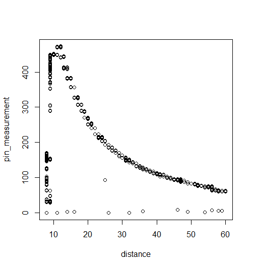
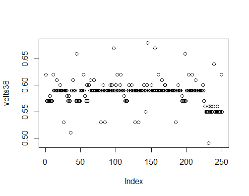
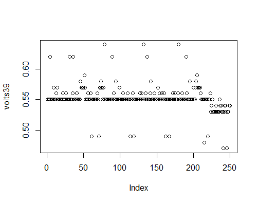
Here is the data from the raw analog numbers:
This is the data with some outliers:
![]()
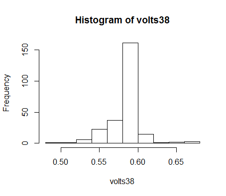
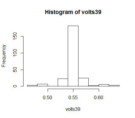
This is the data with the large outliers removed:
![]()
and because I wasn't having much luck getting a good measurement with distances less than 10", this is the data from 10 to 60in:
From this I was able to fit a polynomial regression line:![]()
Call: lm(formula = newPinData$distance ~ newPinData$pin_measurement + I(newPinData$pin_measurement^2) + I(newPinData$pin_measurement^3)) Coefficients: (Intercept) newPinData$pin_measurement 8.992e+01 -6.168e-01 I(newPinData$pin_measurement^2) I(newPinData$pin_measurement^3) 1.796e-03 -1.805e-06 -
Test Setup
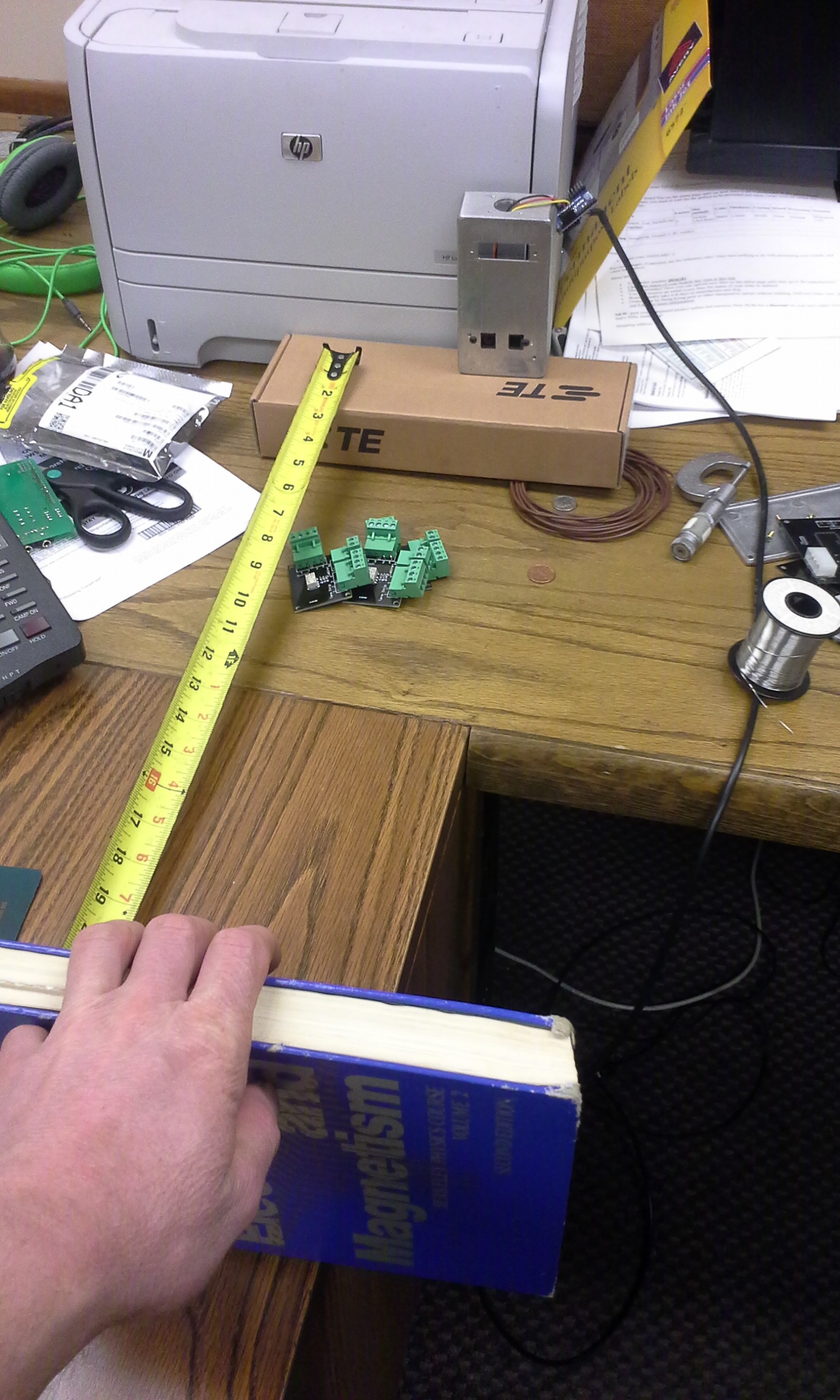
02/05/2016 at 13:01 • 0 commentsThis is the test setup:
![]()
I believe that some of the reason for the variation in the data, other than the outliers, is from the book not being parallel to the sensor, or my wobbling it back and forth, but none the less it worked well enough.
250 samples were taken at each inch.
-
Changes
02/05/2016 at 12:43 • 0 commentsBecause there were problems with compressed air being able to cause mis-reads with the ultrasonic sensors I am trying out the
Sharp GP2Y0A02YK0F.
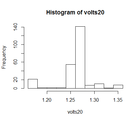
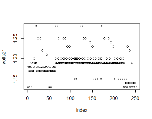
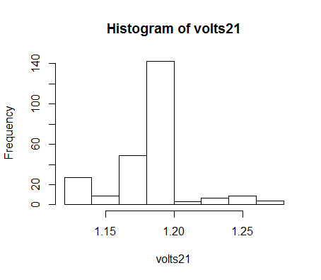
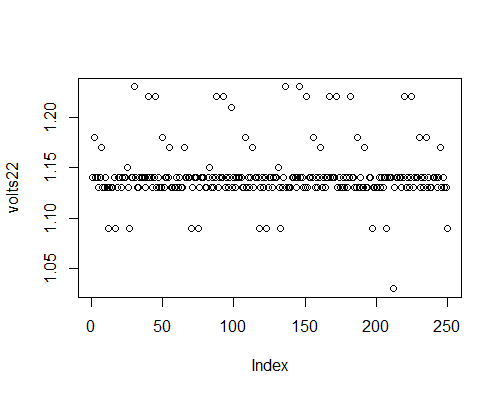
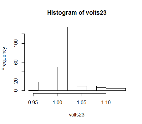
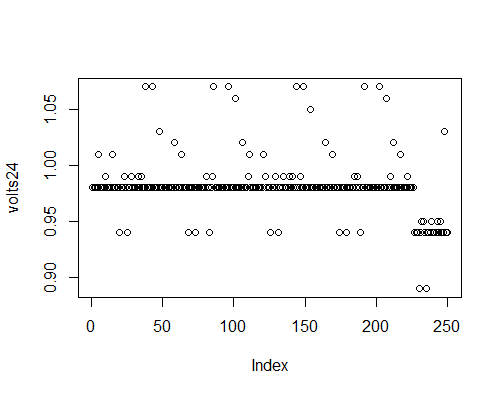
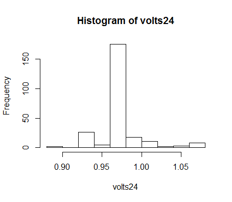
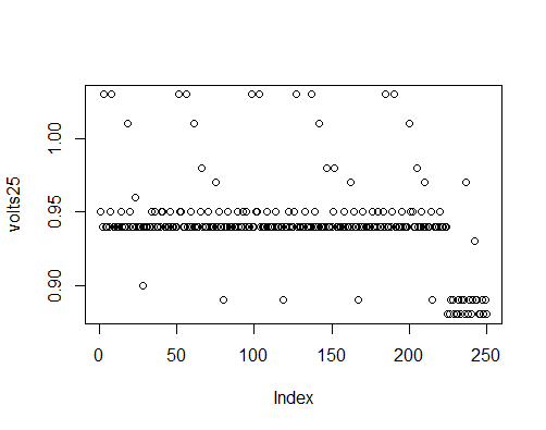
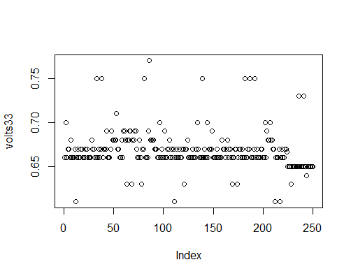
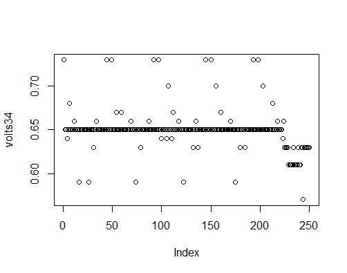
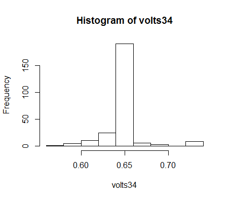
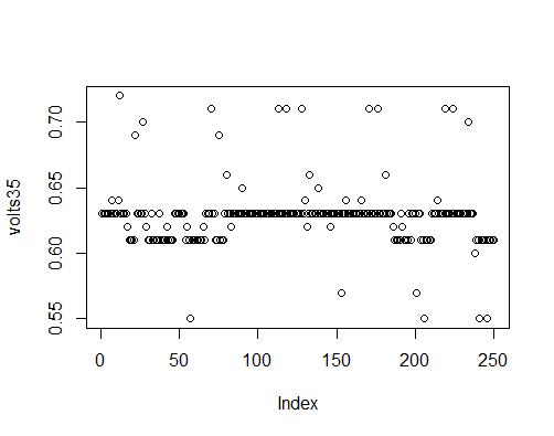
Because there is a wide variation in the output between sensors each sensor has to be calibrated. What I did to get the calibration curve:
Just plugging the sensor in and looking at the raw values it was clear that it would spit out a constant value most of the time with a little noise in the system, so I captured the data between 10 and 39in. because this is the area that I plan on using the sensor in. I calculated the voltage values to check that it was with in spec., and I didn't have something hooked up wrong.
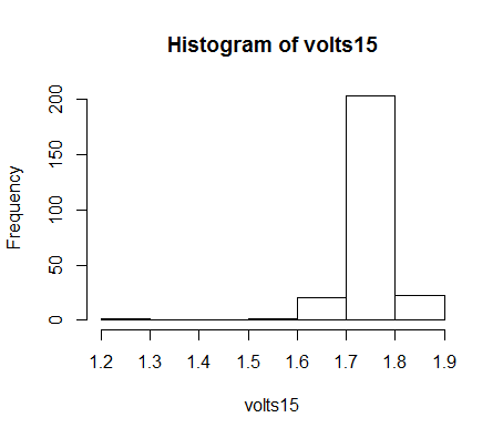
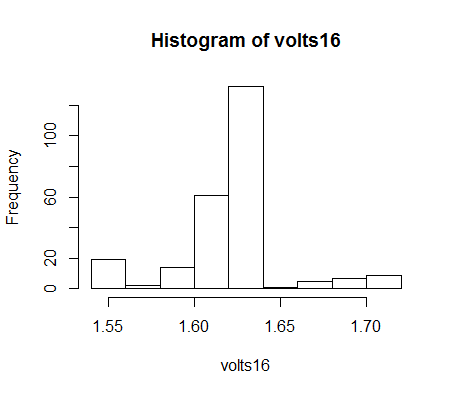
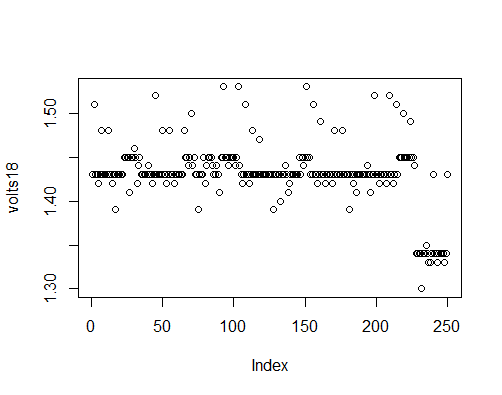
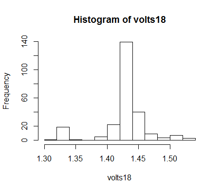
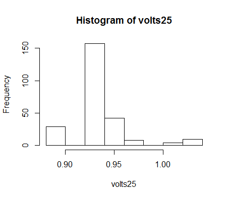
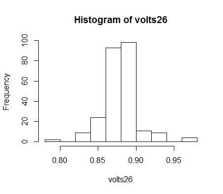
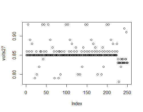
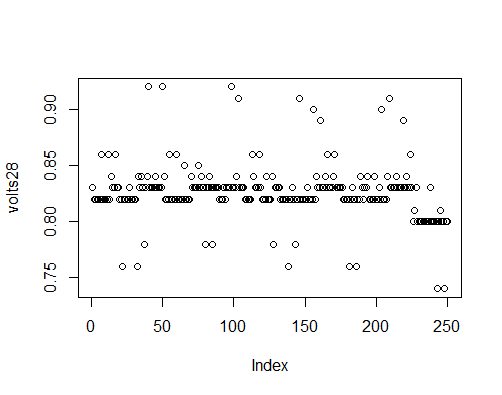
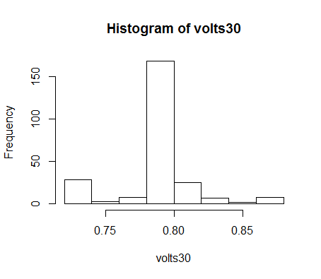
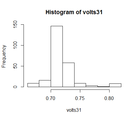
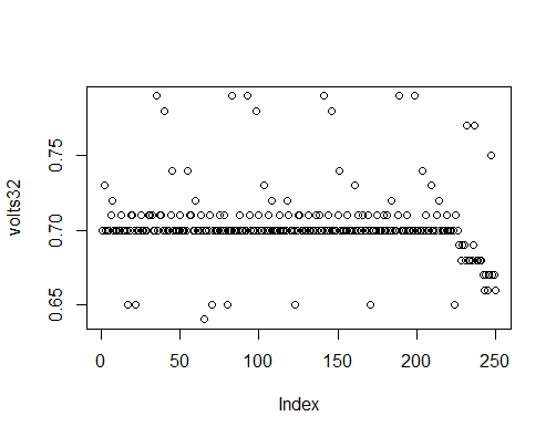
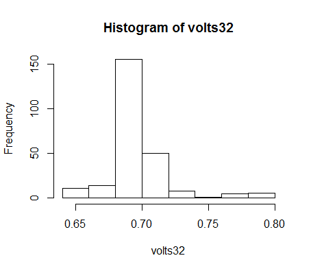
Data:
![]()
![]()
![]()
![]()
![]()
![]()
![]()
![]()
![]()
![]()
![]()
![]()
![]()
![]()
![]()
![]()
![]()
![]()
![]()
![]()
![]()
![]()
![]()
![]()
![]()
![]()
![]()
![]()
![]()
![]()
![]()
![]()
![]()
![]()
![]()
![]()
![]()
![]()
![]()
![]()
![]()
![]()
![]()
![]()
![]()
![]()
![]()
![]()
![]()
![]()
![]()
![]()
![]()
![]()
![]()
![]()
![]()
![]()
![]()
![]()
-
Fit
02/04/2016 at 20:46 • 0 commentsCall: lm(formula = newPinData$distance ~ newPinData$pin_measurement + I(newPinData$pin_measurement^2) + I(newPinData$pin_measurement^3)) Coefficients: (Intercept) newPinData$pin_measurement 8.992e+01 -6.168e-01 I(newPinData$pin_measurement^2) I(newPinData$pin_measurement^3) 1.796e-03 -1.805e-06 -
Current
08/09/2014 at 11:36 • 0 commentsWhat I hope to do here is build the entire system on a single board and hopefully achieve better control of the decoiler and maintain a more constant loop size.
I will try initially to use a triac and proportionally control the rate of the decoiler based on the rate of material being fed into the press. This will not work on all systems because some decoilers only work in an on/off state, but I think that the code should be the same because as the stock material approaches the sensor the controller will drive the triac to a steady on state until change is made.
Also, I am going to try to use one ultrasonic sensor as a transmitter and either two or four as the receiver to hopefully more accurately determine the position of the stock material when it is bouncing. I think what will need to be done here is set the sensor up so that it gets a baseline reading of where the floor is before material is run under it. Interpretation of the signal will take some trial and error though. Twisting is not usually a problem, but the material will sway from side to side, and buck. This returns a reading of the floor or a false reading. I believe that the sway can be solved by keeping the transmitter on until a reading from an acceptable range is achieved (or an error state is reported), and the bucking could be handled in a similar fashion. If the height of material is significantly greater than the previous reading then the transmitter could be left on and the receivers could follow the material until it reaches it's trough and sees another rise, acting on the lowest reading that is not the floor.
-
Original
08/09/2014 at 11:10 • 0 commentsThe original setup simply used a ping))) ultrasonic sensor, arduino, sparkfun ProtoScrewShield, and SSR. There was minimal processing going on. When the material came within a certain range of the sensor the relay would switch and the stock would be uncoiled. Once the stock was a certain range from the sensor the relay would be switched back off.
The problems that I saw with this design was that when the material would bounce around from being fed into the press the sensor would not always register that more material needed to be paid out.
Contactless Loop Controller
Box to control the loop for metal stamping process.