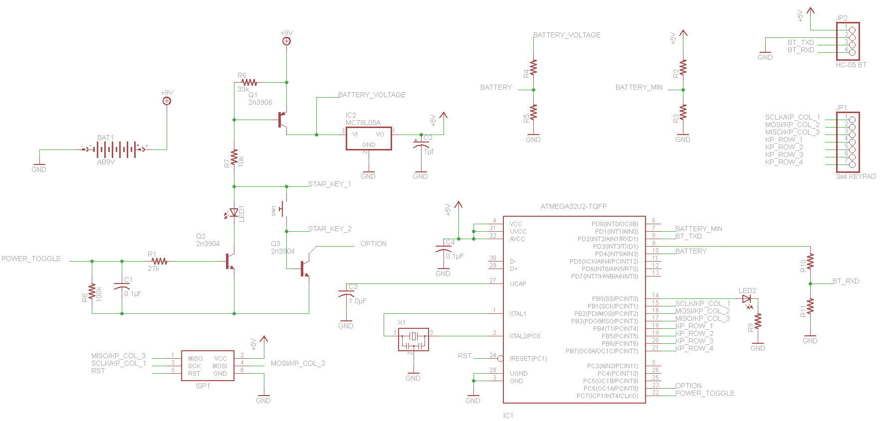
Building the keypad box is very simple. The schematic was designed with eagle and the board was drawn using a french software called "Tracé de CI" which translates to "Printed Circuit Router". The schematics are posted in the project's pictures, but for some reason the site rotated them. I will explain the keypad schematic :
When closing SW1 transistor Q1 closes and connects the 9v battery to the AVR. The first thing the AVR does is it sets PC7 (power toggle) high. Now when PC7 is high , Q2 will close , lighting up the LED and keeps Q1 closed as you release SW1. Q3 is connected to the AVR to PC6 as an option pin, but is not used. This circuit design was taken from the AVR Transistor Tester and is a very good way to save the battery. The BATTERY and BATTERY_MIN use a simple resistor bridge connected to the comparator of the AVR and will detect if the battery is low voltage, flashing the LED before it lets you enter the PIN. The keypad is connected to port B at pins 1 to 7 with the 3 column pins shared with the AVR ISP to program the board. Port B pin 0 is the OUTPUTLED that will flash when keypad is powered on with a low battery, will then remain solid until a connection is confirmed with the master box and then turn off. It will also light when you press a button and when it sends the data to the master box. The RXD pin , PORT D pin 2 is connected directly to the Bluetooth module , while the TXD pin, PORT D pin 3 is going through a resistor bridge to lower the voltage to 3.3v.
I modified the keypad itself so I could isolate the * (star) key and use it as SW1 instead of having it wired to the 4x3 matrix.

The red arrows point to the cut traces. The greenish line shows the column being reconnected after skipping the star key, and the blue lines are the connections to the switch connected to STAR_KEY_1 and STAR_KEY_2 on the schematic. This leaves all 11 other keys working and the star isolated from the rest.
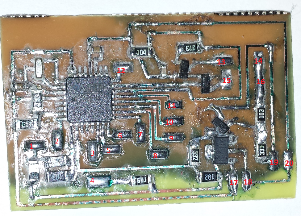
This is definitely not the best looking board I ever made , as you can see this is a double sided board that hasn't etched completely on the other side , but since I'm using just one side , and that the resistant coating was starting to peel off I pulled out the board before it was over etched. I used muriatic acid and peroxide to etch this board, as this instructable shows. This board was at least 7 years old , and I suspect the coating to be somewhat out of date. I got much better result using a more recent board for the master box. I wanted to keep the board as small as possible and avoid jumpers so instead I placed pads all over where the wires are needed for the keypad , Bluetooth, LEDs and 9v connector. Also not shown here is a 1µf tantalum capacitor connected to the 5v line. Once populated I used the pads to connect the ISP connection and flash the module. The keypad, star key and the POWER LED need to be connected otherwise the board will not power on. To flash the module you will need to hold down the star key during the entire flashing process because the MCU cannot keep the transistor closed while it is being programmed. You could also just connect a wire instead of a switch. I recommend using the female pin connector cable that came with the Bluetooth module so you can easily unplug and switch modules, because the keypad box is used to prepare both the master and slave Bluetooth modules, so you will need to swap them.
Here is the "pinout" of my board :
- SW1 is 15 and 16
- POWER LED is 13 and 14 , with 13 being the cathode.
- Bluetooth is : 5V: 17 GND : 18 RXD: 1 TXD : 2
- OUTPUT LED is 3 and 4 , with 4 being the cathode.
- ISP : CLK : 5 MOSI : 6 MISO : 7 RESET : 12 GND : 18
- KEYPAD : COL_1 : 5 COL_2 : 6 COL_3 : 7 ROW_1 : 8 ROW_2 : 9 ROW_3 : 10 ROW_4 : 11
- 9V Connector : 9v: 19 GND : 20
Once everything is connected it is time to flash the AVR with the SETUP compiled code and setup the Bluetooth modules.
Here is everything crammed in its box, without the AVR ISP connection:
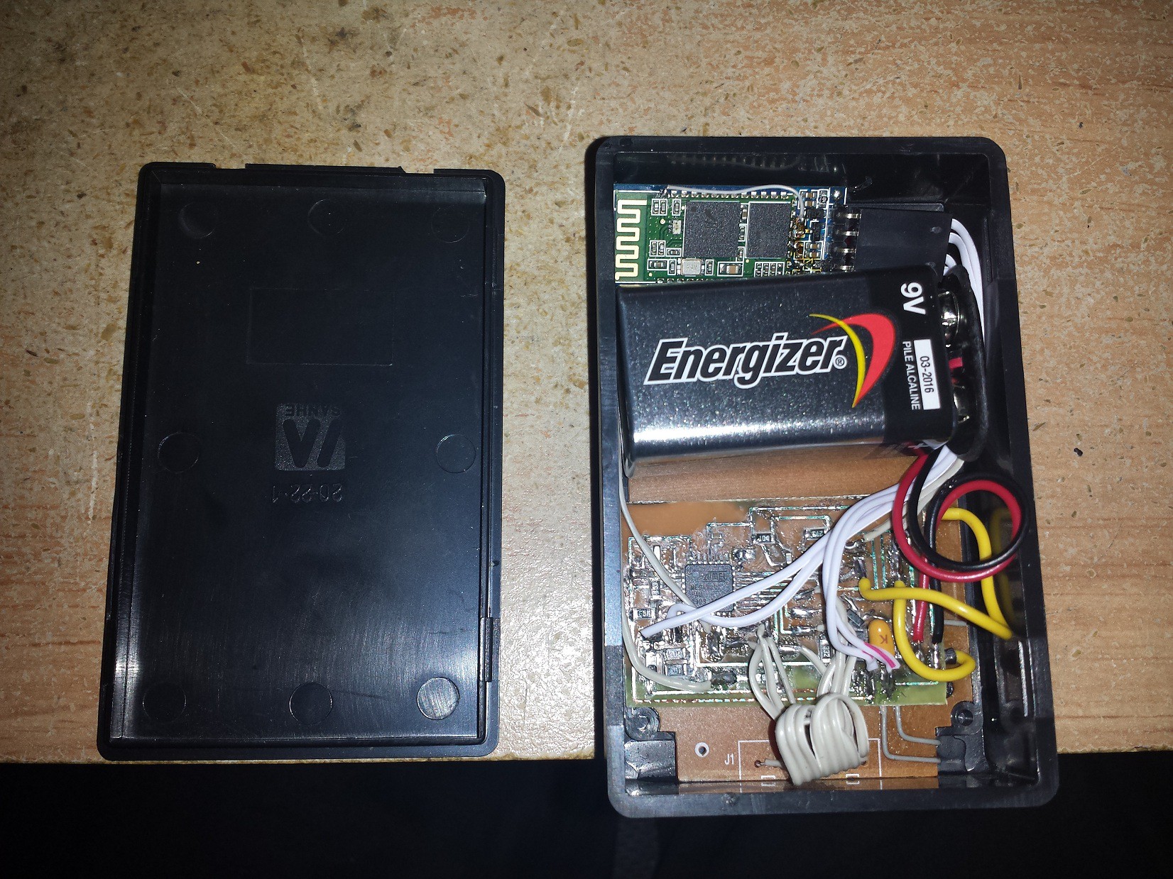
The keypad is super glued to the case and the board is glued to the keypad. The Bluetooth module and battery are left floating but with the back cover closing tight with the battery, nothing moves.
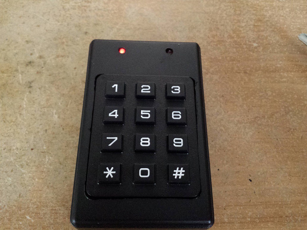
The keypad boxed powered up, and synced (right LED turned off). Press the star key, both LEDs will turn on. Wait for right LED to turn off. Once off, enter your 4 digit PIN and the door unlocks.
Discussions
Become a Hackaday.io Member
Create an account to leave a comment. Already have an account? Log In.