 tshen2
if you're playing music from your computer, and it's coming out of amplified speakers, the signal chain probably looks like this:
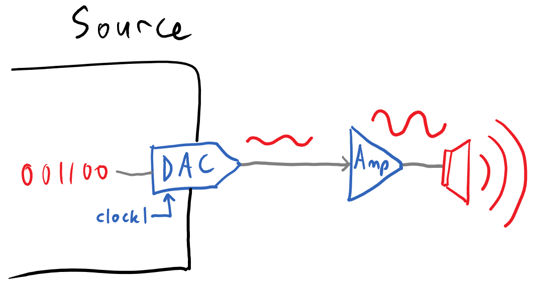
the music is stored digitally in your computer. it gets converted to analog audio by the digital-to-analog converter (DAC) which is in your soundcard (or external). the analog audio is embiggened by the amplifier, which then pushes your speakers.
When you stick a DSP in the middle, the picture looks a bit more stupid.

as before, the music is stored digitally, and is converted into analog audio by the DAC. but the DSP only understands digital audio, so you need an analog-to-digital converter (ADC) to convert the analog signal back into digital. and after the DSP has done its work, you need another DAC to go back to analog. this is not good because every converter degrades the audio signal. why can't we remove the first DAC and ADC, and send digital audio directly into the DSP?
the main problem is synchronous clocking - both the transmitter and receiver must be using the same clock. here, the source is using clock1 and the DSP is using clock2. you cannot simply force the DSP to use clock1, because all the DSP's frequency filters are controlled by its clock, and clock1 can be very inconsistent! if clock1's frequency shifts by 2%, the DSP's frequency filters will shift by 2%. if clock1's frequency is 44.1kHz when the DSP is expecting 48kHz, things could get very, very broken.
while journeying through the intertubes, i found a potential solution - the CP2114 by Silicon Labs. it is a 'USB-to-I2S Digital Audio Bridge', i.e. a chip which connects to your computer's USB port, and speaks a digital audio protocol (I2S) which the DSP understands. how does this solve the 'different clocks' problem?
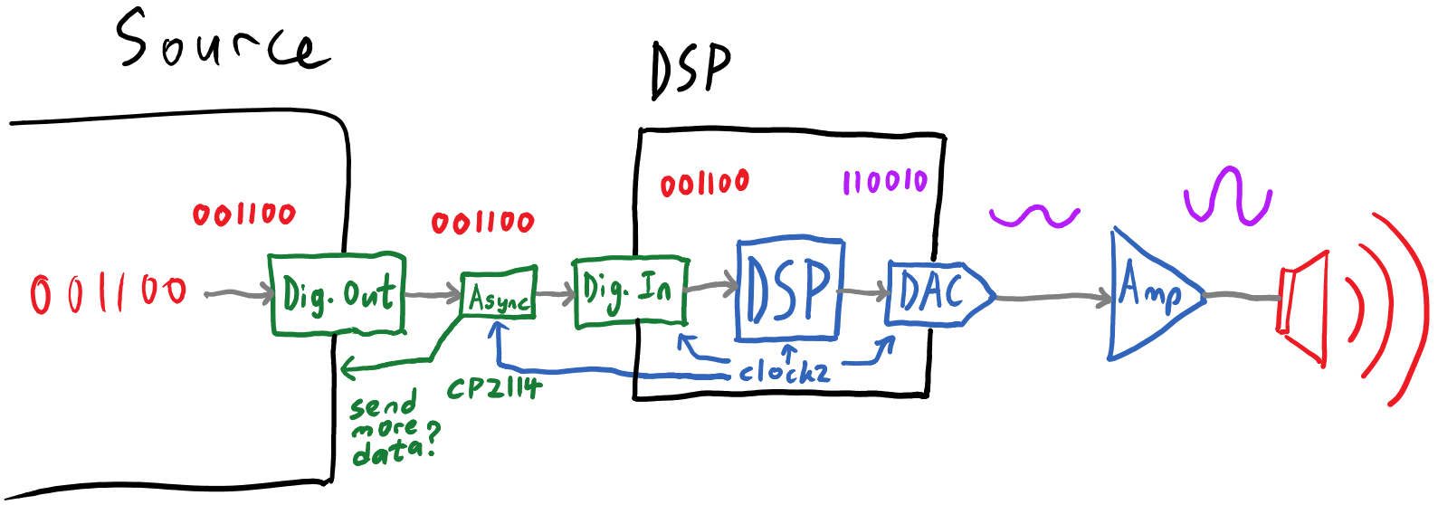
the CP2114 is an 'asynchronous' USB audio device. this means a few things:
- it uses its internal clock (clock2) which is shared with the DSP.
- it tells the source (e.g. computer) to prepare data for a fixed sample rate (48kHz).
- due to clock mismatch, the source will send data too rarely or too often. the CP2114 can tell the source to 'send more/less data' as necessary.
in this scheme, it doesn't matter that the source and DSP don't share the same clock. the source is forced to resample and transmit the data at 48kHz, and if its clock doesn't match up exactly with the CP2114's clock, the CP2114 can tell it to slow down or speed up.
as for bit-depth, the CP2114 only supports 16-bit audio, which is rather low. however, it also supports sending 'volume control' information as a separate 8-bit signal. since the main advantage of 24-bit audio vs. 16-bit audio is having more bits to throw away for dynamic range, that separate 8-bit volume control makes the low bit-depth more palatable.
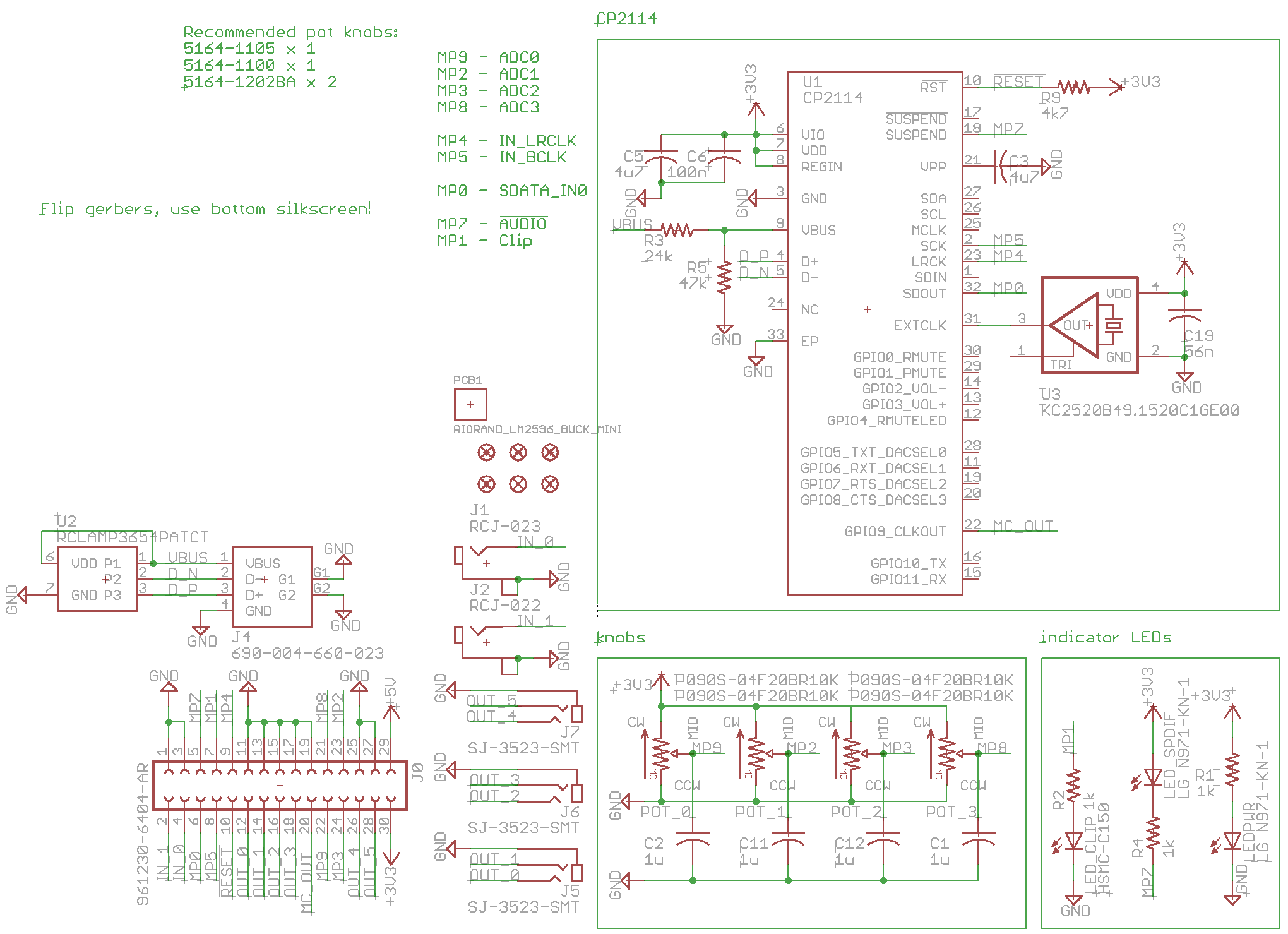
so - let's make a board to plug the DSP 01 into a CP2114.
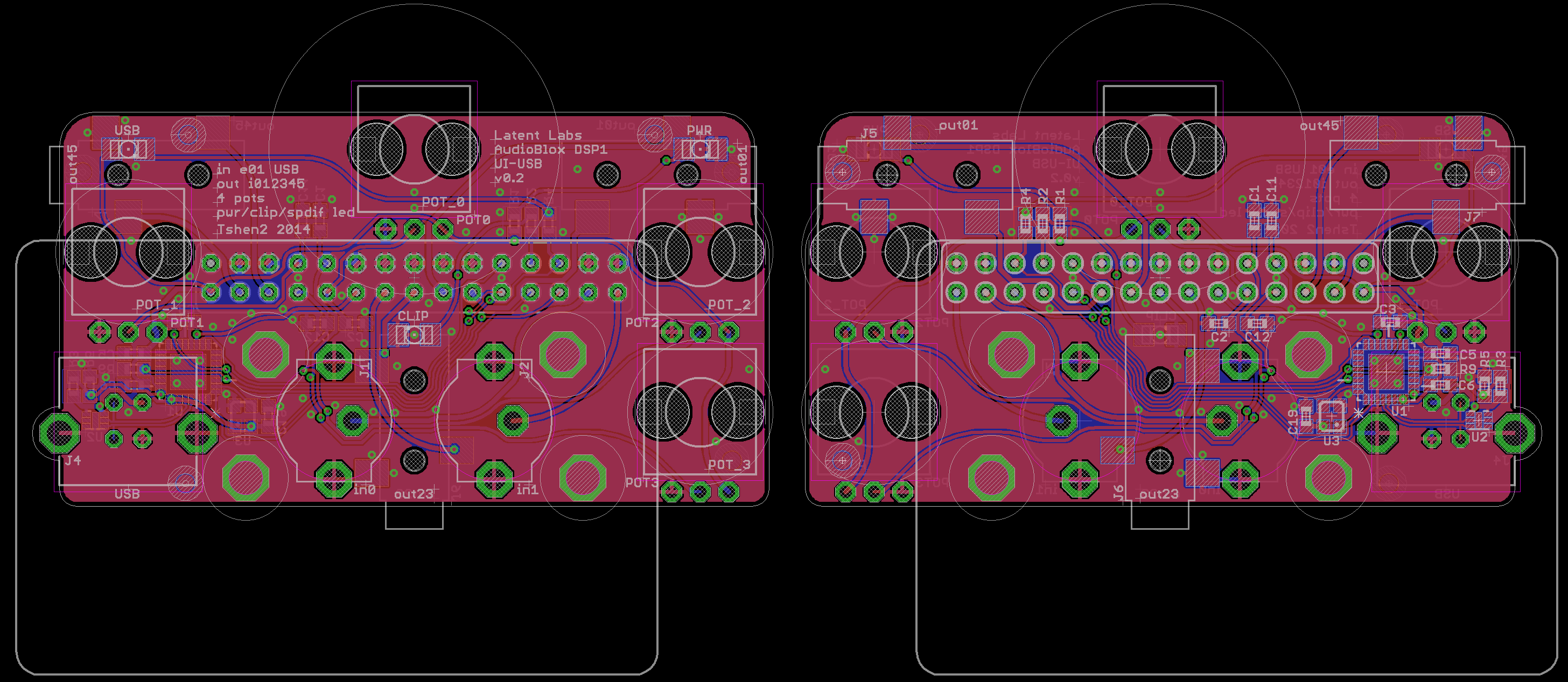
[PCB layout - front (left) & back (right).]
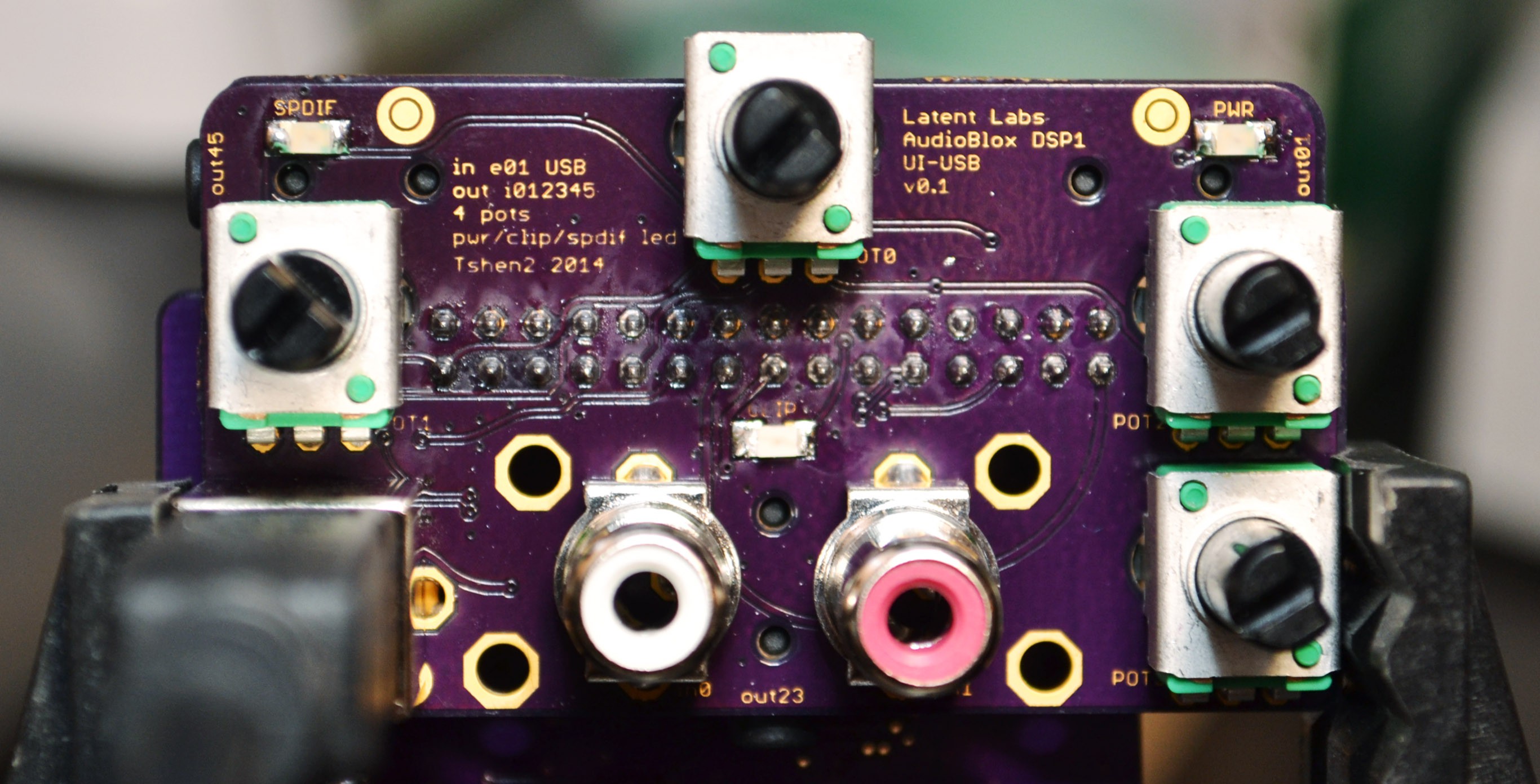
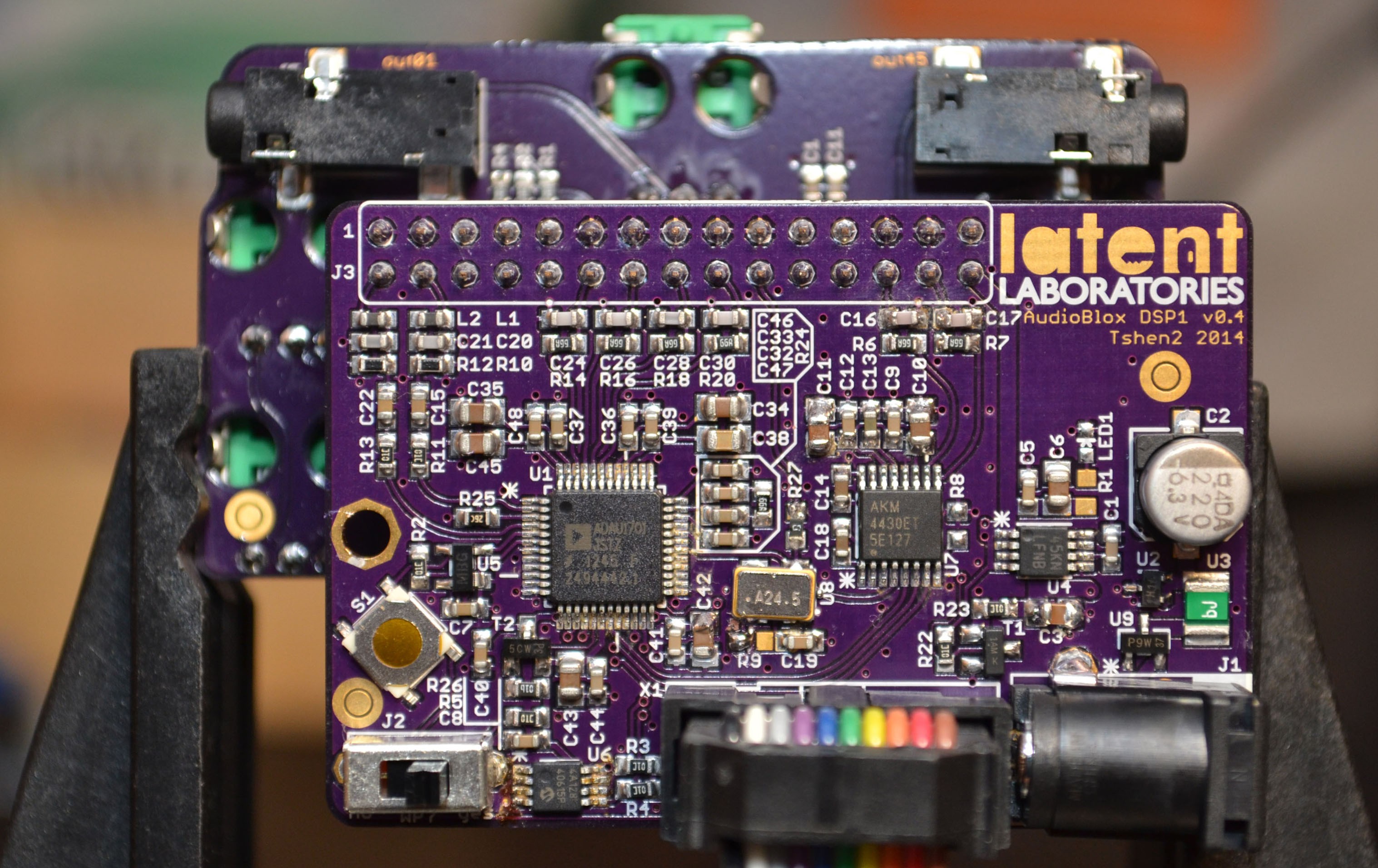 [and a DSP 01 board at the back!]
does it work? nope.
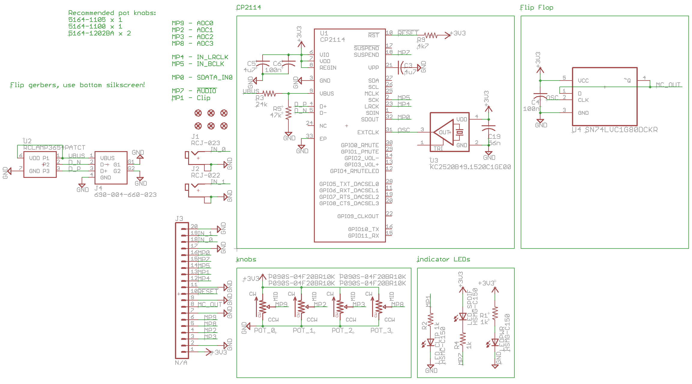
the DSP 01 wants a 24.576MHz clock signal. in order to produce that clock, i put a 49.152MHz clock on the CP2114 board (pictured above) and tried to use the CP2114's internal clock dividers to halve that clock to 24.576MHz for the DSP 01. the problem is, the CP2114's clock dividers only work when the CP2114 is connected to a computer's USB port. the DSP 01 wouldn't be able to run at all if no USB source was present.
so i redesigned the board, this time with an external clock divider (using a D-flipflop):
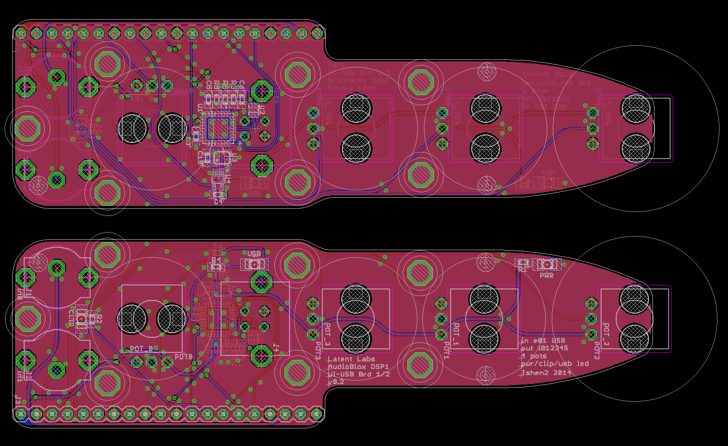
[PCB layout - front (lower) & back (upper).]

does it work now? still nope.
but why?
as i've mentioned, the CP2114 is supposed to be a 'USB-to-I2S Digital Audio Bridge'. the DSP 01 accepts digital audio input through an I2S bus, so I assumed they'd be able to talk to each other. the thing is.. the CP2114 does I2S wrong.
here is a screenshot from the I2S spec:
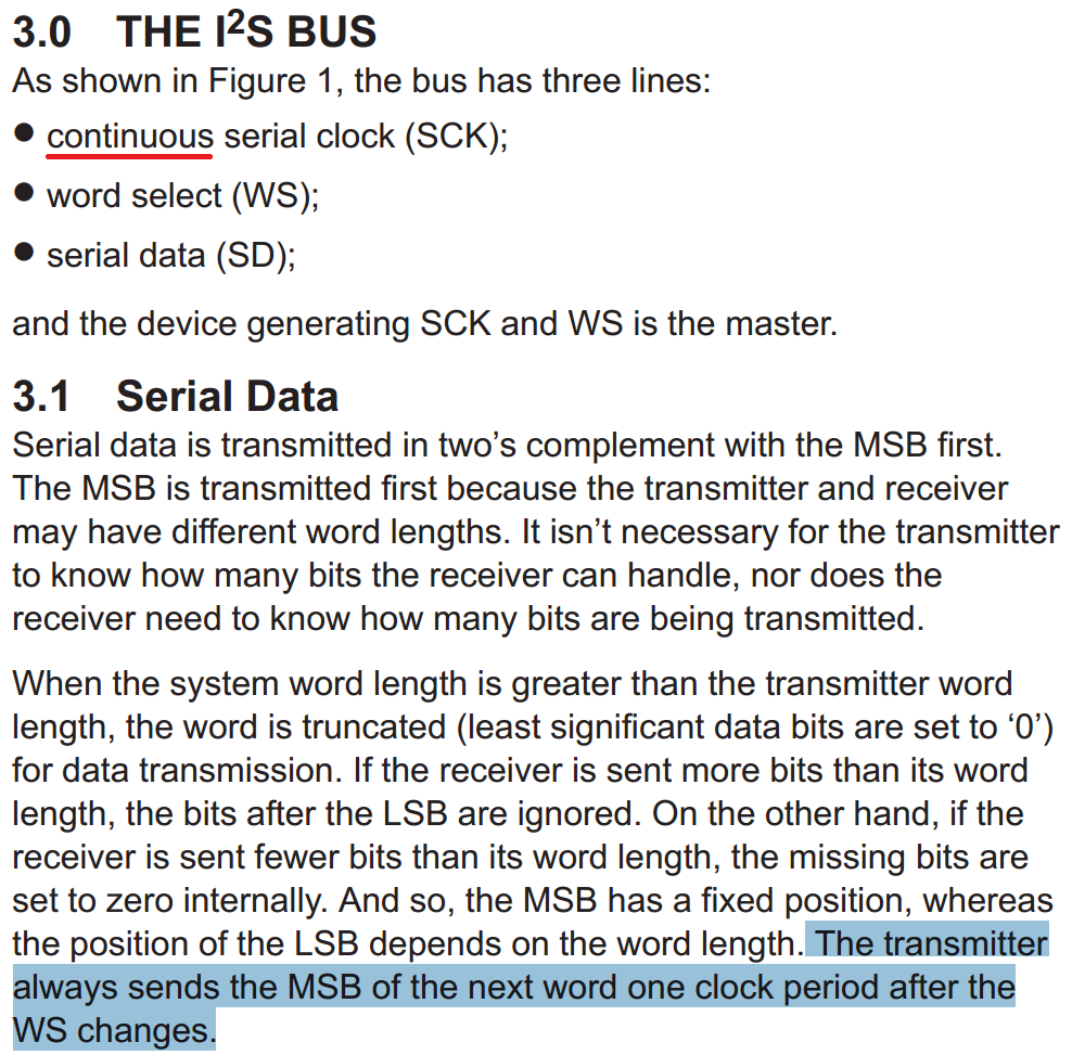
let's pay attention to these two points:
- the serial clock (SCK) must be continuous.
- the 'transmitter always sends the MSB of the next word (on the SCK) one clock period after the WS (Word Select) changes'.
now, let's compare this to actual SCK and WS signals from the CP2114.
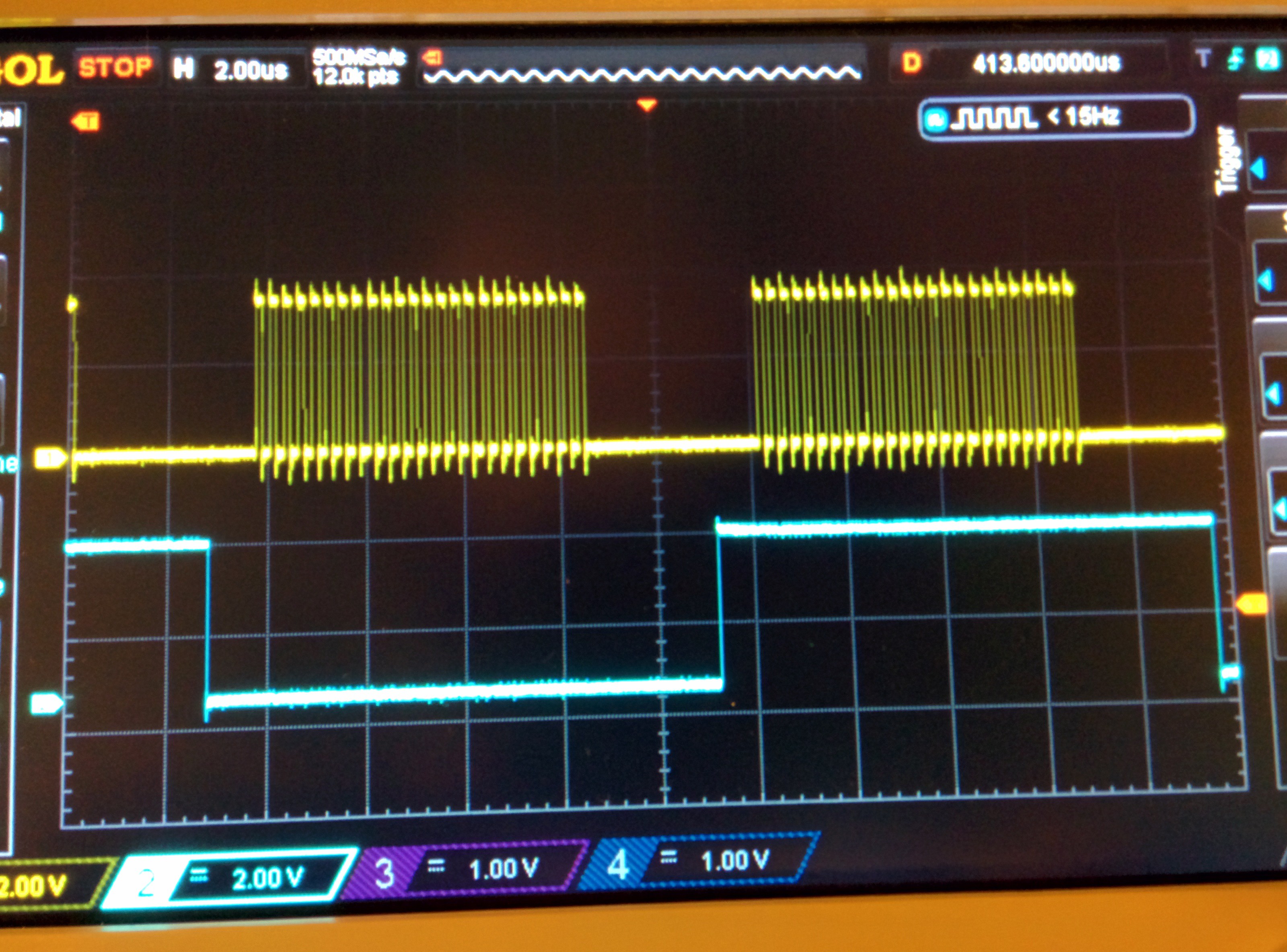
[CP2114 I2S bus: SCK (upper) and WS (lower)]
the CP2114 fails on both listed criteria:
- the SCK is obviously not continuous - instead it appears in bursts, with an inconsistent time-delay after each WS clock edge.
- the MSB of the next word (on the serial data line, not shown) appears when the SCK appears. but the SCK doesn't start one clock period after the WS changes. so the MSB of the next word doesn't appear at the right time either!
rest assured that i have used the CP2114 correctly, and tried every conceivable setting which might get it to work.
i contacted Silicon Labs about this obvious deviation from the I2S spec, and got this reply:
"It is possible that the device you are using has requirements outside the I2S specification, you would need to ask the manufactures (sic) of that device if this is the case. It's also possible that this has nothing to do with that delay, but from the scope shots you sent there are no obvious issues."
this is after they'd linked me to the same I2S specification which i used to debug the problem!
so, i presume they are aware of the problem, but are unable or unwilling to fess up to it, or do anything about it for the time being.
either way, it doesn't really matter. unless big changes are made, the CP2114 is dead to me.
moving on..
UPDATE: Silicon Labs got back to me! this is what they said:
"The CP2114 actually implements I2S with a SPI, some firmware, and a few other things. Because of that you get some artifacts like this. Unfortunately the (sic) are limitations of the hardware and I don't see a way to work around them in the device firmware. I will run it by the the firmware guys just to be sure."
either way, i still can't use the CP2114. it seems like an easy fix in hardware - add a bit of logic to buffer the serial data, and output it synchronously during the next sample clock. you'd get a one-sample delay but who cares. of course, you can't do that in firmware..
next update: i use resampled SPDIF to get a working digital input!
Tshen2 2015
Discussions
Become a Hackaday.io Member
Create an account to leave a comment. Already have an account? Log In.