 Jazzmyn
-
11Step 11
Customize Tri-Fold Board Part 2
Bring me the knife!
![]()
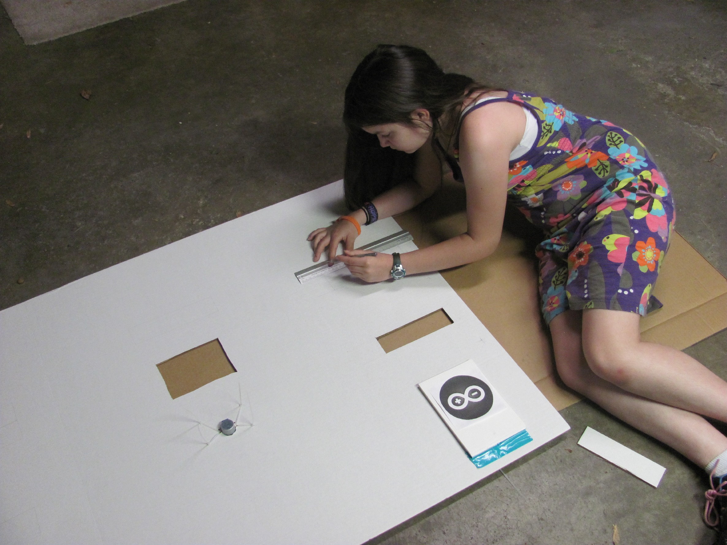
- Measure twice
The tri-fold board will need many cut outs. I cannot stress enough how critical measurement is at this point. Mark where all the cuts will be in pencil and check with a ruler before getting the knife. Regret is a horrible feeling. Use a metal ruler when you make your cuts.
![]()
- Stepper motor
In the center section of the tri-fold find the center and trace the outline of the stepper motor. The stepper motor will stick out the front of the board in order for the photo wheel to lay flat against the back of the board. Attach the stepper motor using zip ties threaded into the board.
![]()
- Servo door
The servo will be attach to the back of the board and will need a slot for the arm to move up and down. Make this slot a little bigger than you think because the arm can get stuck when the door is all the way open or closed. Attach the servo using zip ties as well.
- Photo wheel window
Measure from the center of the wheel to the top of the photo and copy this measurement on to the tri-fold board from the center of the stepper motor. This will be the top of the window. Then place a photo on the board with the top centered on your mark and trace around it. With the marks in place it is time to cut.
![]()
- Stencil signs
The location of the stencil signs is up to you and is dictated by your project. Make rectangular cutouts to fit the light boxes you made earlier. I used a T square to help keep the lines straight.
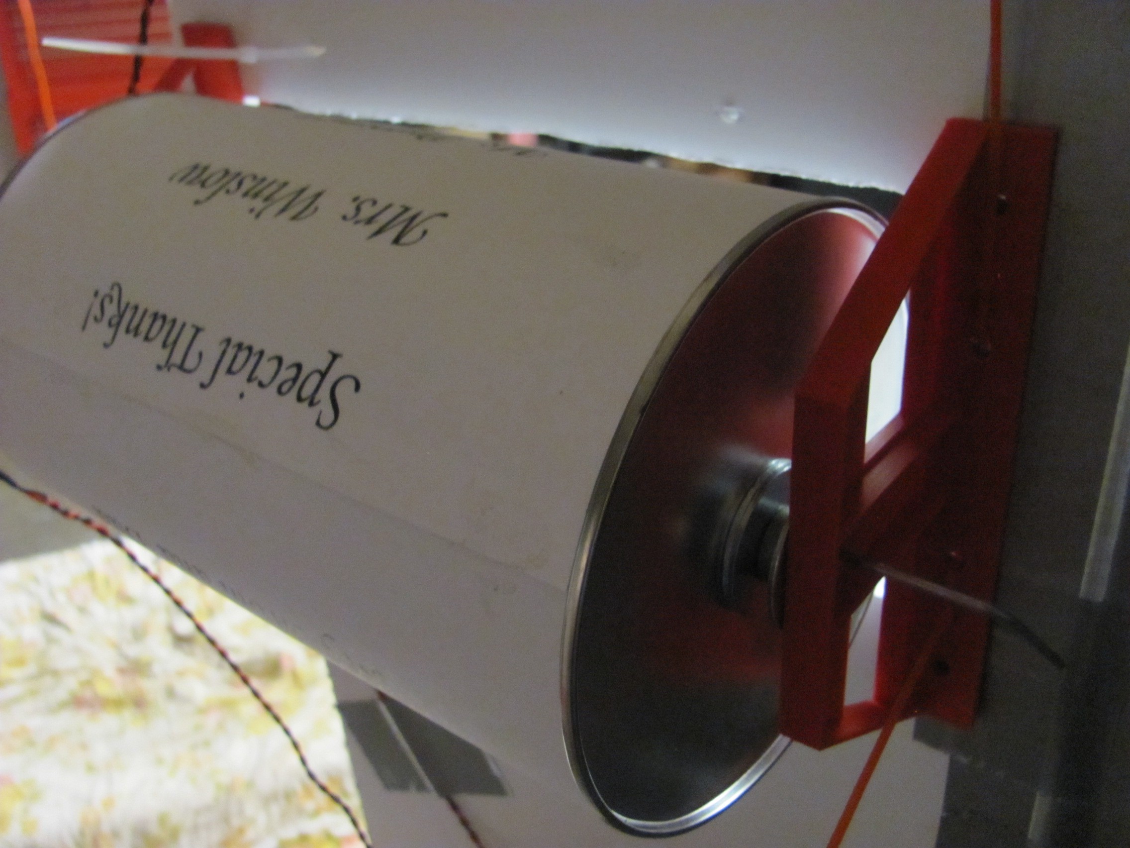
- Credit spinner
I placed the credit spinner on one of the extra foam core side panels. Make this cutout smaller than the can you used so it will act as a frame for the credits. You will need to make it big enough to prevent the wheel from getting stuck. If you are in doubt about how big to cut start small and make the hole bigger as needed.
-
12Step 12
Assembly Part 1
Hardware
- Servo Arms
The servo arms are made of metal coat hanger wire. The wire is bent to allow screws to attach to the servo horn and hold the wire in place. You will need one arm for the door and one for the attention getter sign.
![]()
![]()
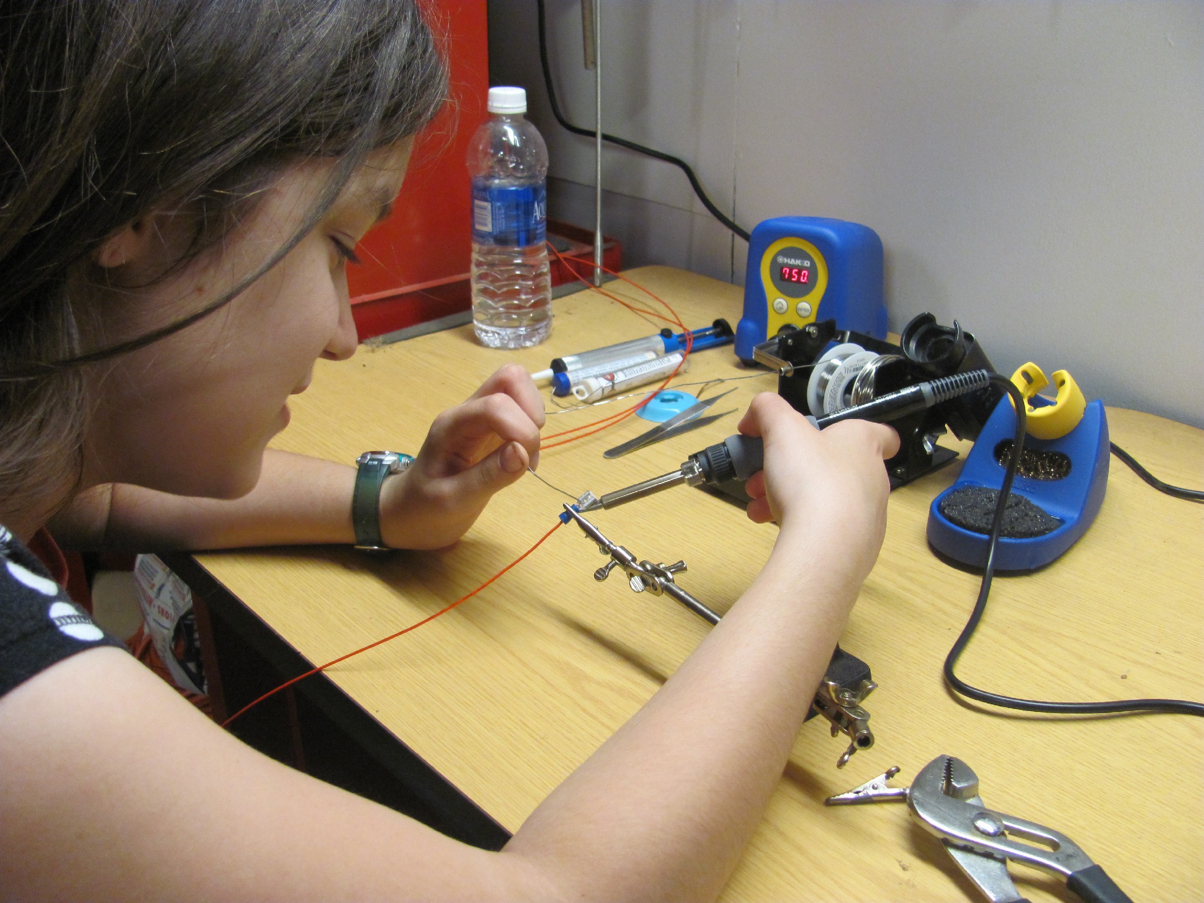
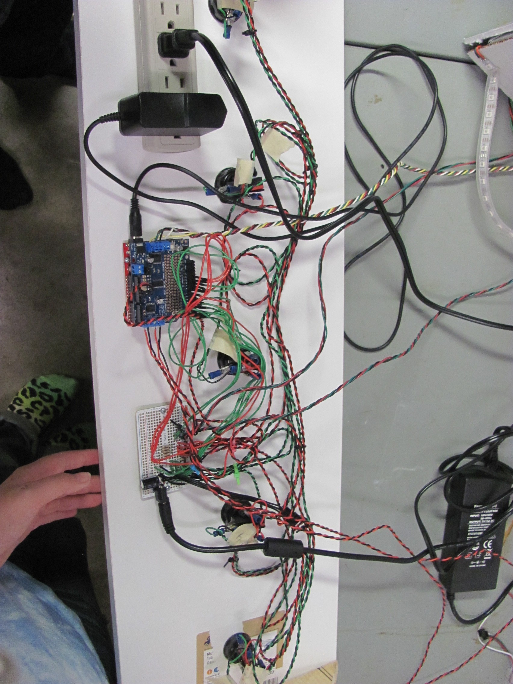
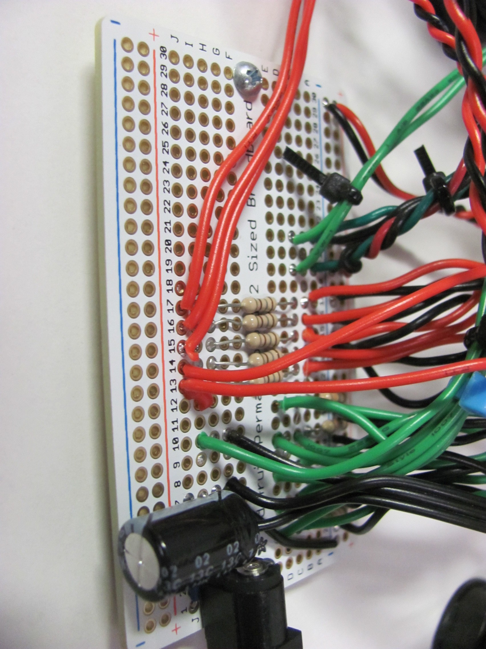
- Soldering
Make good notes on how your breadboard setup works and transfer it onto a proto board. I used a adafruit perma proto half size breadboard. adafruit.com/products/571 Included are the resistors for the LED lights, debounce resistors for the buttons, and power socket for the neopixels with a filter capacitor.
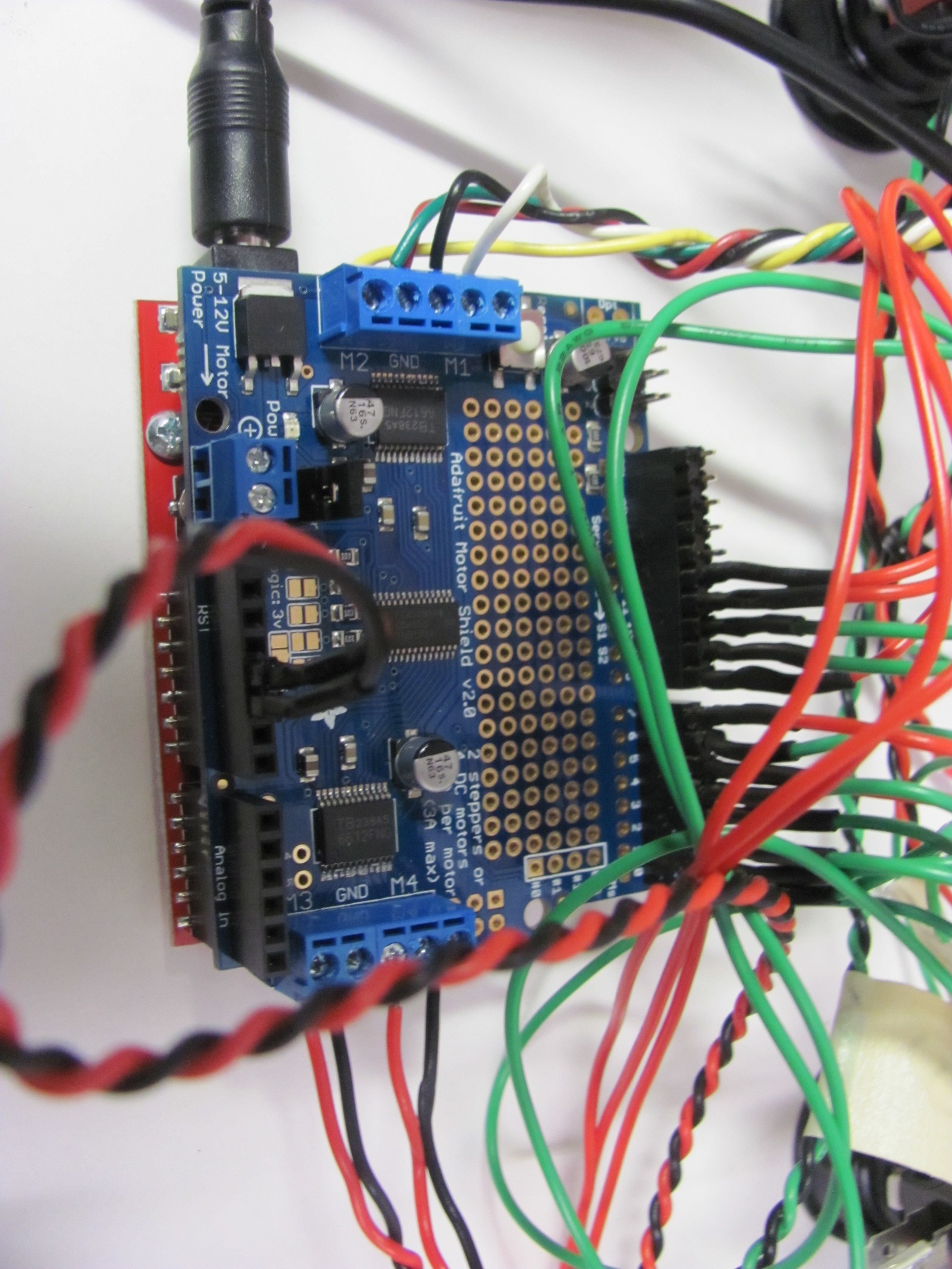
I used an adafruit motor shield that also required some soldering.adafruit.com/products/1438 I needed some stacking headers and they were soldered in place as well.
![]()
![]()
![]()
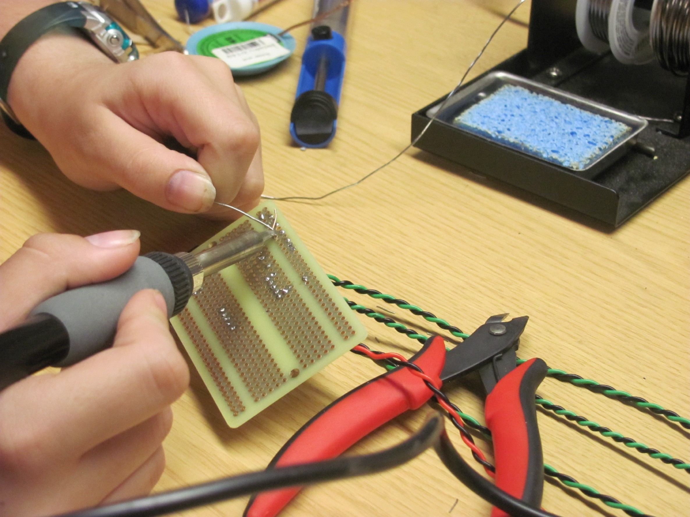
- Wiring
The wires for all the buttons are soldered directly to the perma board. The other end having quick disconnect connectors for the buttons. The buttons have different size connections for the LED's and button. I used sparkfun.com/products/11487 for the connections. I soldered the connectors to the wires. You will need four wires for each button. There is also a JST connector soldered on for the neopixels. adafruit.com/product/578
-
13Step 13
Assembly Part 2
3d Printed Parts
![]()
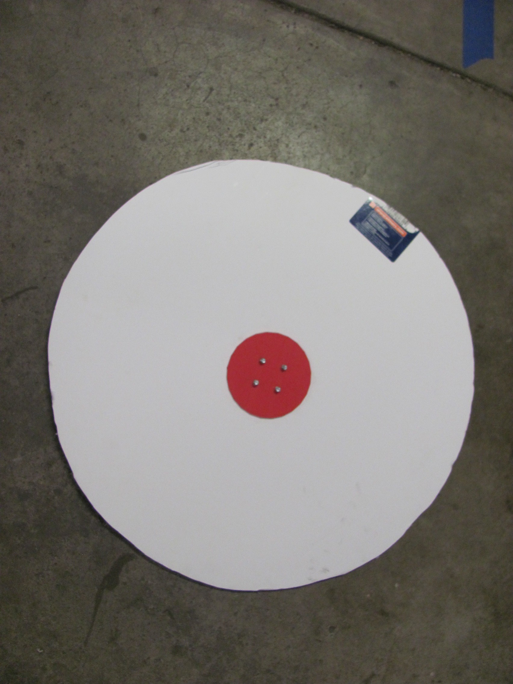
- Photo wheel
The photo wheel uses a two piece clamp style hub. This helps to spread out the turning force on the foam core to prevent t from becoming lose on the stepper motor. The two parts are attached using four screws. Then press fit onto the stepper motor shaft.
![]()
- Photo spinner
The photo spinner has a hub that is hot glued onto the bottom. This attaches to the small hobby DC motor. This hub has four grippers that push into the foam core to help hold into place. There is also a bracket for the DC motor that is attached to the board using zip ties.
![]()
![]()
- Credit spinner
The credit spinner is the most complicated part on the board. It took many different revisions to get it to work. The final product is still not perfect and could use some more thought. There are two frame pieces for each side of the spinning oatmeal can that attach to the board using zip ties. One of these has a holder for the DC motor. There is also two gears. The large gear is supper glued to the oatmeal can. The other fits onto the DC motor. The whole assembly is held together using a piece of coat hanger wire through the middle of the can and into the frame pieces. This is one of my favorite ideas but is very troublesome to get it to work. The large gear must be perfectly centered when it is glued in place. Mine is not. The motor will get stuck if it is not right. I also have trouble getting it to spin so it is overpowered at the start and then spins to fast to read. A stepper motor would have been a better solution than the DC motor. This would of given me more control of the motors speed.
![]()
-
14Step 14
Test it:
In House
![]()
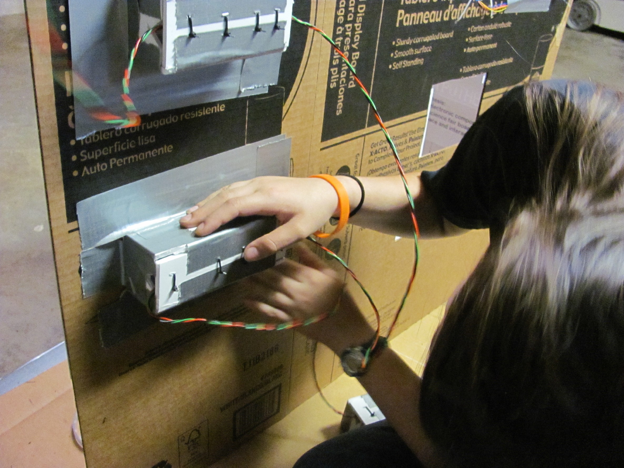
- Dose it work
Test each feature over and over.Are there any problems? Make adjustments to the parts or code as need be. I changed the servo travels after I had them mounted to the board. Another issue was the connection to the stepper motor twisting causing the photo wheel to get stuck. This was fixed with duck tape. I also changed some of the delays to better fit the project.
- Will it last
Keep it running for at least a couple of hours to see if there are any other issues. The last thing you want is for something to get stuck and damage a part during the fair. It is best for this to happen at home so you can fix the problem. It may will need to run all day and into the night unattended.
In Public
- Setup problems (Don't Panic!)
My power and ground wire came disconnected from the Arduino during the move form home to the fair.When I put it back in place it was not in the right pins. When I turned it on all sorts of new and wierd things started to happen. (Now Panic!) It took me a while checking all the connections and scratching my head before I realized this simple mistake. I worked my way down all the connections in my notes before I found it. Have I mentioned to take good notes?
![]()
- Did it hold up?
The photo wheel came off when two boys decided to team up and slam all five buttons at once shaking the wheel lose. It was a easy fix but to prevent it happening again I put some rubber cement on the stepper motor shaft to help hold everything together. Lesson learned boys don't push buttons they slam them but that's okay.
- Feedback
Both parents and students loved the project and there was a line most of the night. Buttons are a big hit. My observations is that the more moving parts the better. More information on how it was built was requested so this hackaday.io project entry is the answer. One parent wanted to know where to buy the kit for the board until I showed him my custom wire job. Better wire management was his recommendation.
-
15Step 15
Improve It
- What did work
The attention getter sign drew in the crowd and the buttons kept them busy. The most pushed button opened the servo door. More doors would of been nice. The LED's gave the project a attractive glow and set it apart from the other projects.
- What did not work
The wheel fell off and needed glue to help hold it in place. The wheel also dragged on the board and got off time. So I added spacers to the stepper motor to prevent it from dragging. I put delays in for the stencil lights to draw attention to different sections of the board. The delays were to long and people kept trying to push another button before the delay ended. My wires were to long and were a pain to manage during setup and tare down.
![]()
-
16Step 16
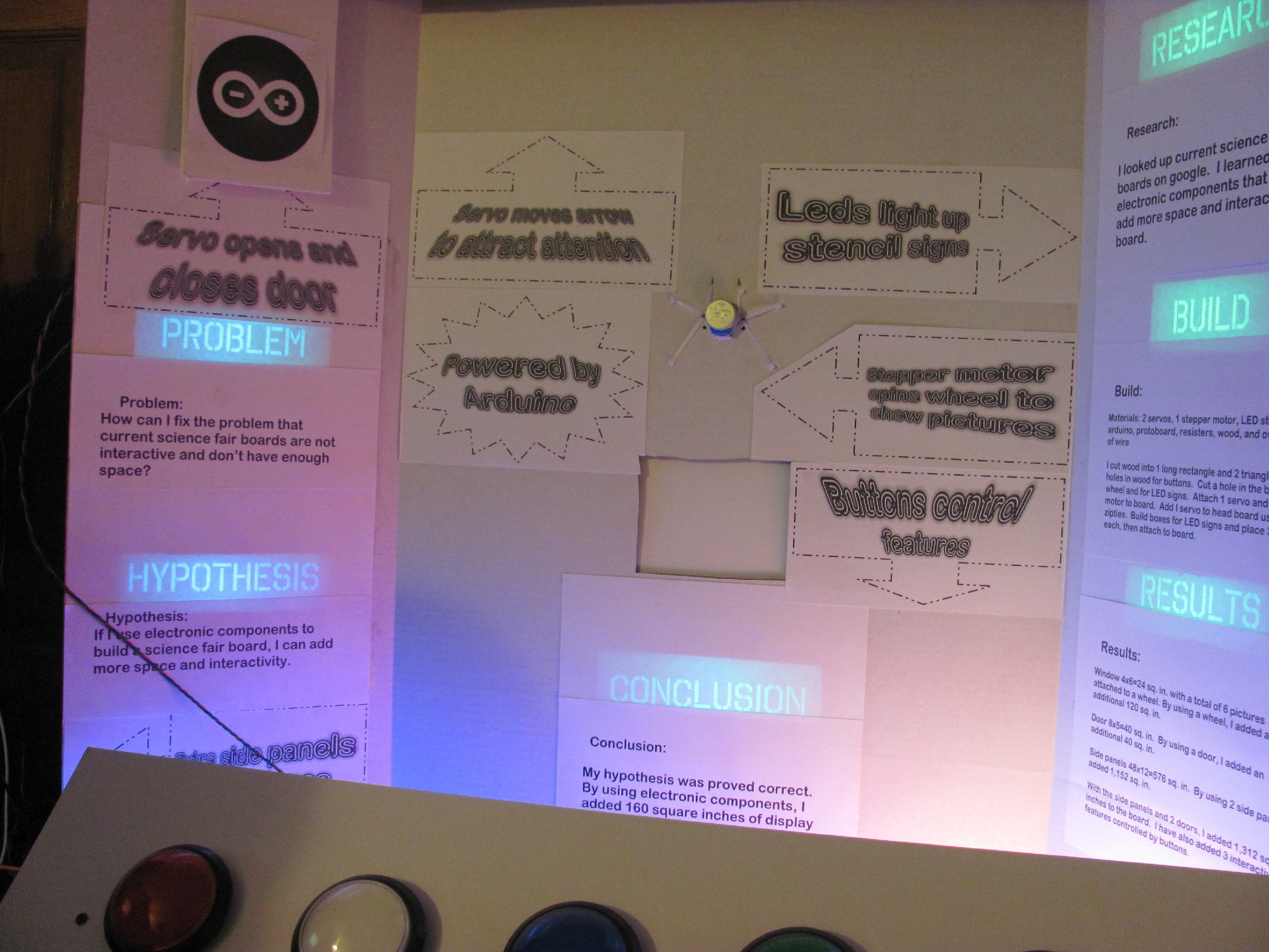
Final Results
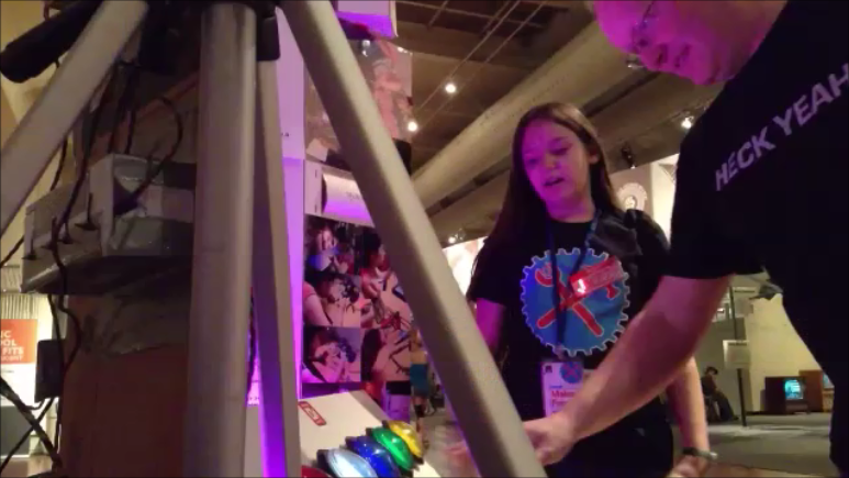
Ben Heck of the benheckshow.com stopped by and gave it a try
![]()
- At Maker Faire Detroit 2014
With the problems fixed I was off to Maker Fair Detroit. I handed out 500 business cards and ran out on the second day. The allure of buttons proved to strong for many of the walkers by. One little girl was inspired to learn that this project was built by a girl. That little girl made all the struggles I had building it worth while. Suggestions for more features were many. My favorite was to add sound.
![]()
-
17Step 17
Future improvements
- More interactivity
More buttons large and small to control new features. A big dial would be cool what to use it for is still a mystery to me. Sound would be a great improvement. LED bar graphs to represent changes in data over time would be a good feature.
- Better wire management
I need to shorten the wires and bundle them together.I could also use to label the wires so I don't confuse them during setup. This would add to the professional look to the project.
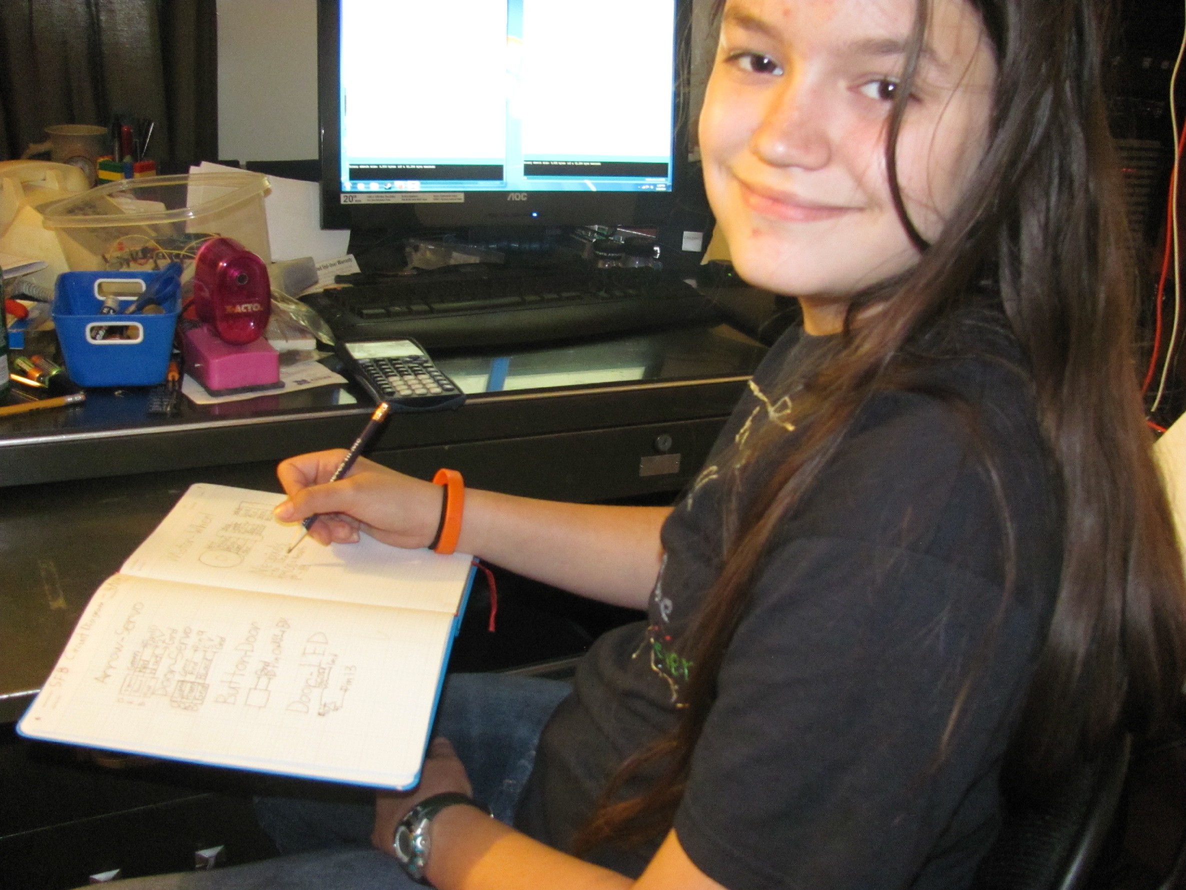
- Improve documentation
My notes saved me more times than I can count. I need to go back and get them better organized. They are scattered across a few different notebooks. I should of taken more photos and video during the build. It is hard to stop working when you are on a roll but I missed a bunch of important steps along the way. Lesson learned the hard way.
-
18Step 18
Help Me Spread the Word
I have entered this in a contest but if I see someone that has built one in the wild then I will feel like a true winner!
I have posted my files on hackaday.io, thingiverse.com, and linked to my web page engineeringwithjazz.com and youtube account. Please stop by and give me a view. I could use my readers help to get onto the main hackaday page or maybe even onto makezine.com. Please help me spread the word by sending emails and telling anyone that might be interested in making a interactive science fair board about this project.
Thank you for reading I hope you were inspired to make a interactive science fair board for your next fair. I want to see other people take this idea and make it there own. We need to get people excited about science and engineering. Remember to never stop improving!
Jazzmyn
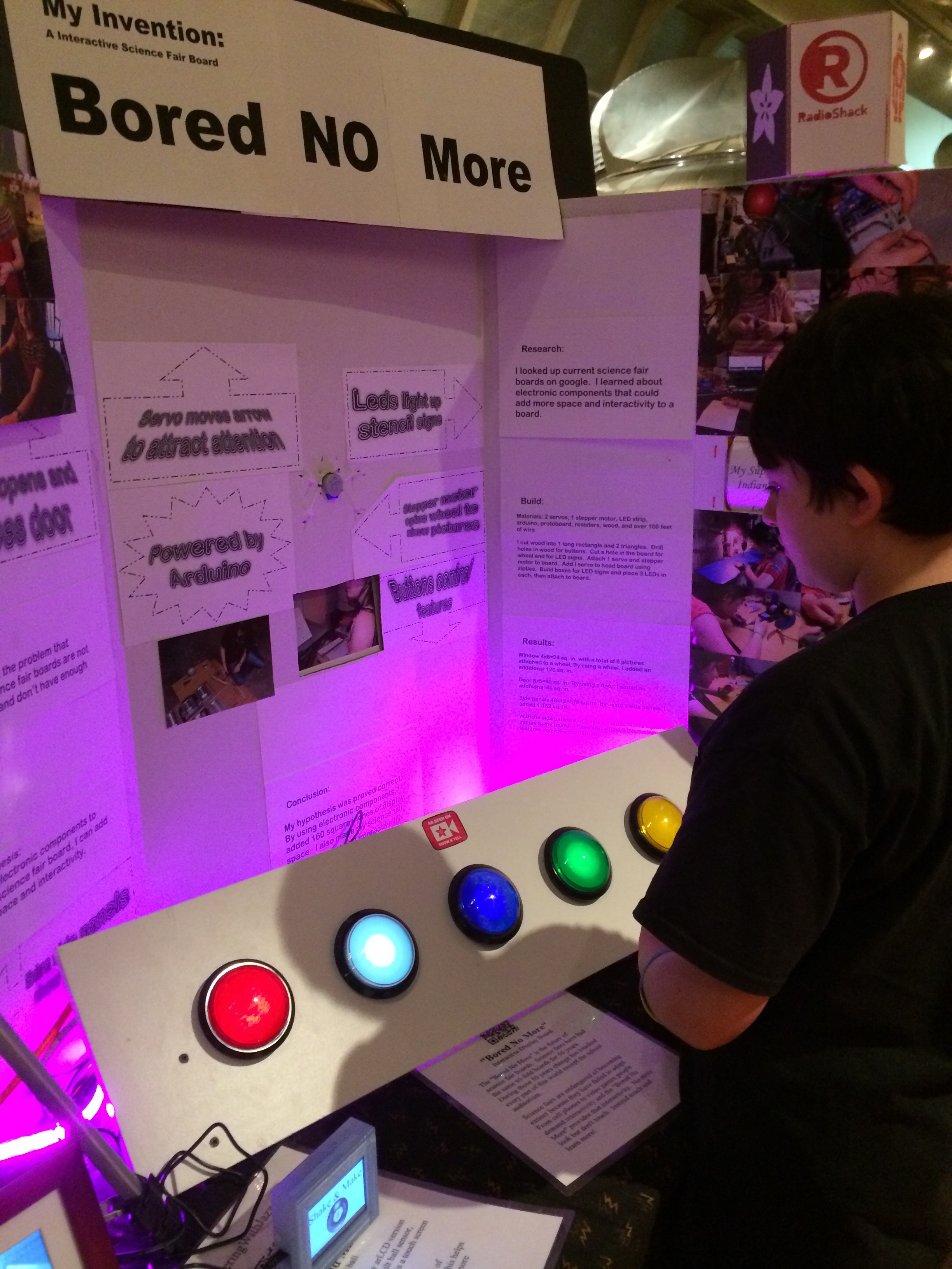
Bored No More
Interactive Science Fair Board Using Arduino, big buttons, servos, and motors create excitement while interacting with science.


Discussions
Become a Hackaday.io Member
Create an account to leave a comment. Already have an account? Log In.