 Anderson Antunes
A few months ago I had the idea to create mechanical connectors to be used as building kit for testing circuits before permanently soldering the components, or as a construction toy kit (anyone interested?).
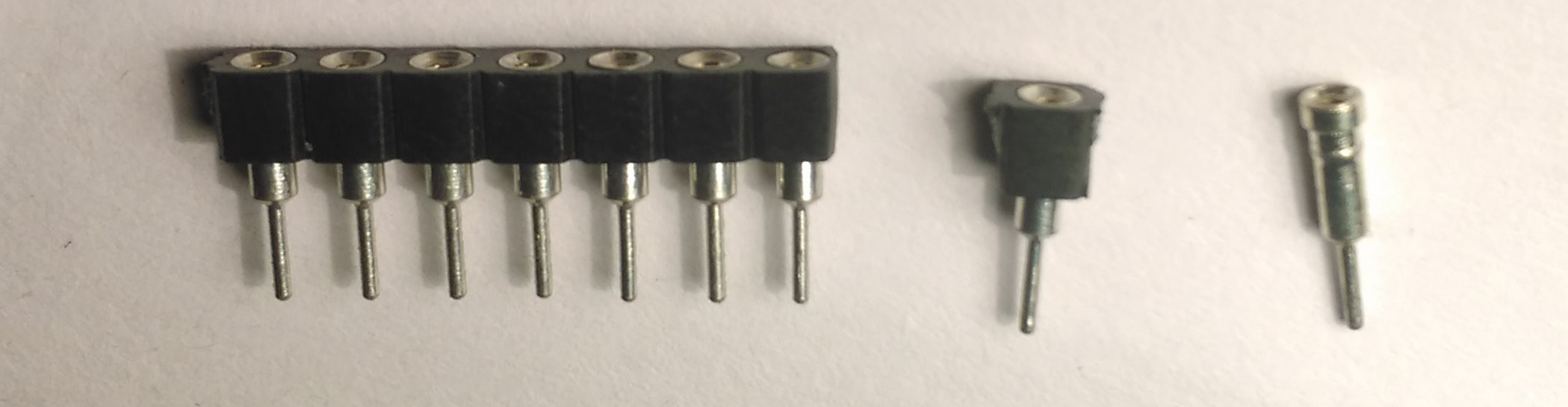
Firstly I choose the right type of terminal: Machine pin header (how they are called?) are perfect because they make good mechanical and electrical connection with the component pluged in.
I even thought in using a 3D printed mold to create pieces of high temperature silicone to keep the terminal pins from falling apart while soldering them together, but it turns out that it is not so simple, I never had made molds nor worked with silicone casting, and also high resolution 3D printing is expensive. So I started thinking in a cheaper solution using some things that I had laying around.
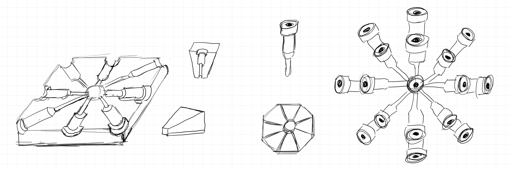
Then I thought in holding the terminal pins in place using some rods, but they had to be keep in place by some kind of structure, at first I conceived a small hollow sphere with some holes to fix the rods, but I remembered that the heat of the soldering iron would melt the structure, so I designed a structure with a shape of a rhombicuboctahedron, but only with the main supports for the rods.
For the materials, I wanted something mechanically stable, so I buyed 1kg of PLA plastic to use with my 3D drawing pen (I still do not have a 3D printer). It took more than seven hours to manually draw approximately 4 layers of material and join together all the 45 pieces that make the structure. The result was strong enough to kept its shape even when I tried to bend it. I made the holding rods with cotton swab (that will be replaced with some metal rods latter), round female pins, blu-tack, paper, scotch tape and high heat epoxy putty. The blu-tack plays an important role in the apparatus: It made possible to adjust the position and orientation of the rods, compensating the irregularities of the main structure.
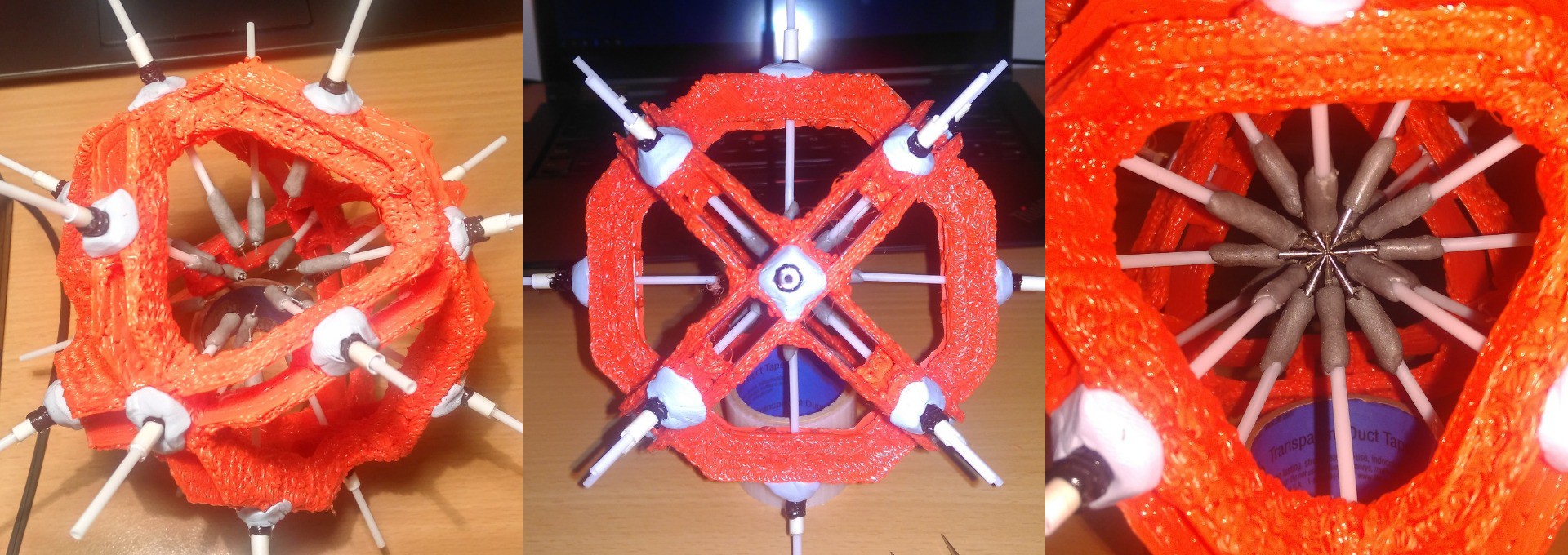
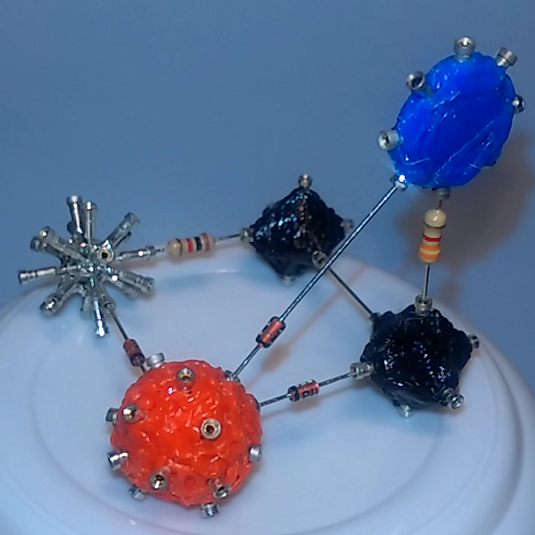
The final build made possible to align all the pins and solder them together to create the custom connectors. I made three types of connectors with the materials that I had in my room:
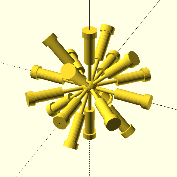
- Two spherical with 18 connections (one naked and one with red PLA)
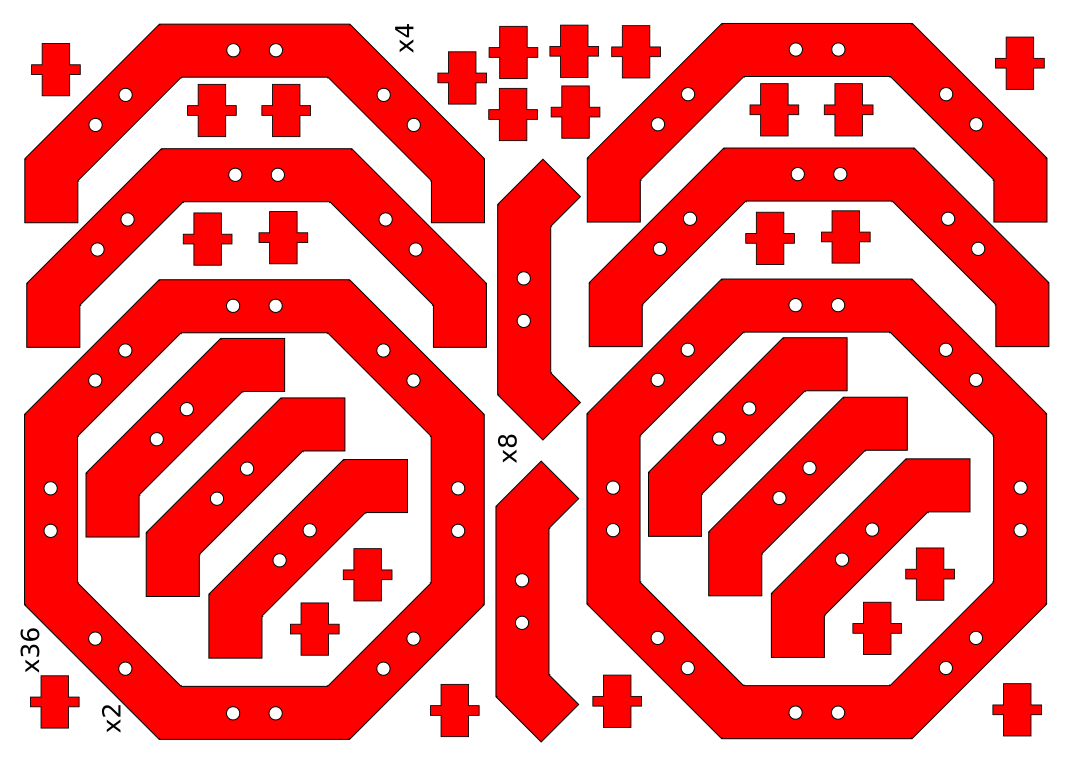
- One octagonal (flat) with 8 connections (blue PLA)
- Two cube-shaped with 6 connections (black PLA)

The results were great, but I think it still have lots of room for improvements. All fitted together smoothly and produced good quality connections. There is not enough connectors to build some interesting, but I already ordered more headers to start building some more. I will also create some connectors with two and three isolated layers for connecting small two-terminal components and transistors.
Let me know if you liked the idea, and feel free to give me suggestions! :D
Discussions
Become a Hackaday.io Member
Create an account to leave a comment. Already have an account? Log In.
I dig it! And now finally a use for all those machine-pins I saved when cutting 16-pin DIP sockets down to 14 ;)
Are you sure? yes | no
Yes! That's the spirit! :)
Are you sure? yes | no
awesome hack ! :-)
Are you sure? yes | no
Thanks! I'm glad you like it :)
Are you sure? yes | no