 SUF
SUFI was thinking, looking around a lot before I designed and built the current motor driver circuit. I wanted to use something cheep, something I can learn from.
The current one is working, but I was thinking, how can I make it a little bit faster. When I designed the current one, experimented lot on the breadboard, but not used ltspice to simulate the circuit. When it was finished, I needed to tweak it, here and there, to be able to reduce the noise for the clear measurement signal.
Now I'm trying to get faster switching, to reduce the heat generated by the MOSFET.
First of all I run a simulation of the original circuit.
The circuit:
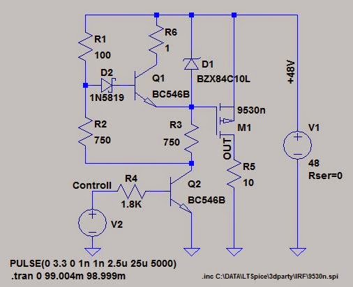
And the result:
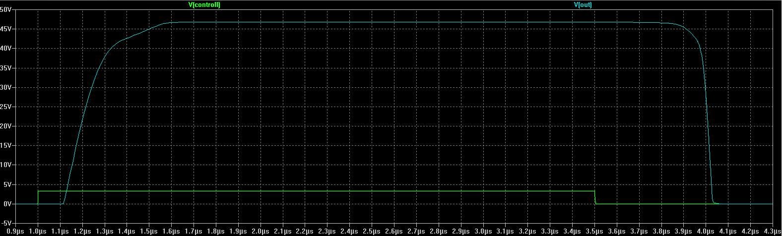
As you can see the the timing results:
Switch on time: ~500ns
Switch off time: ~500ns
After 2-3 weeks of continuous (in my spare time, what I not really have to much) simulation, changing components, pursuing different ideas, finally I created a little bit better one.
The circuit:
And the result:

And the timing:
Switch on time: ~30ns
Switch off time: ~100ns
Much better.
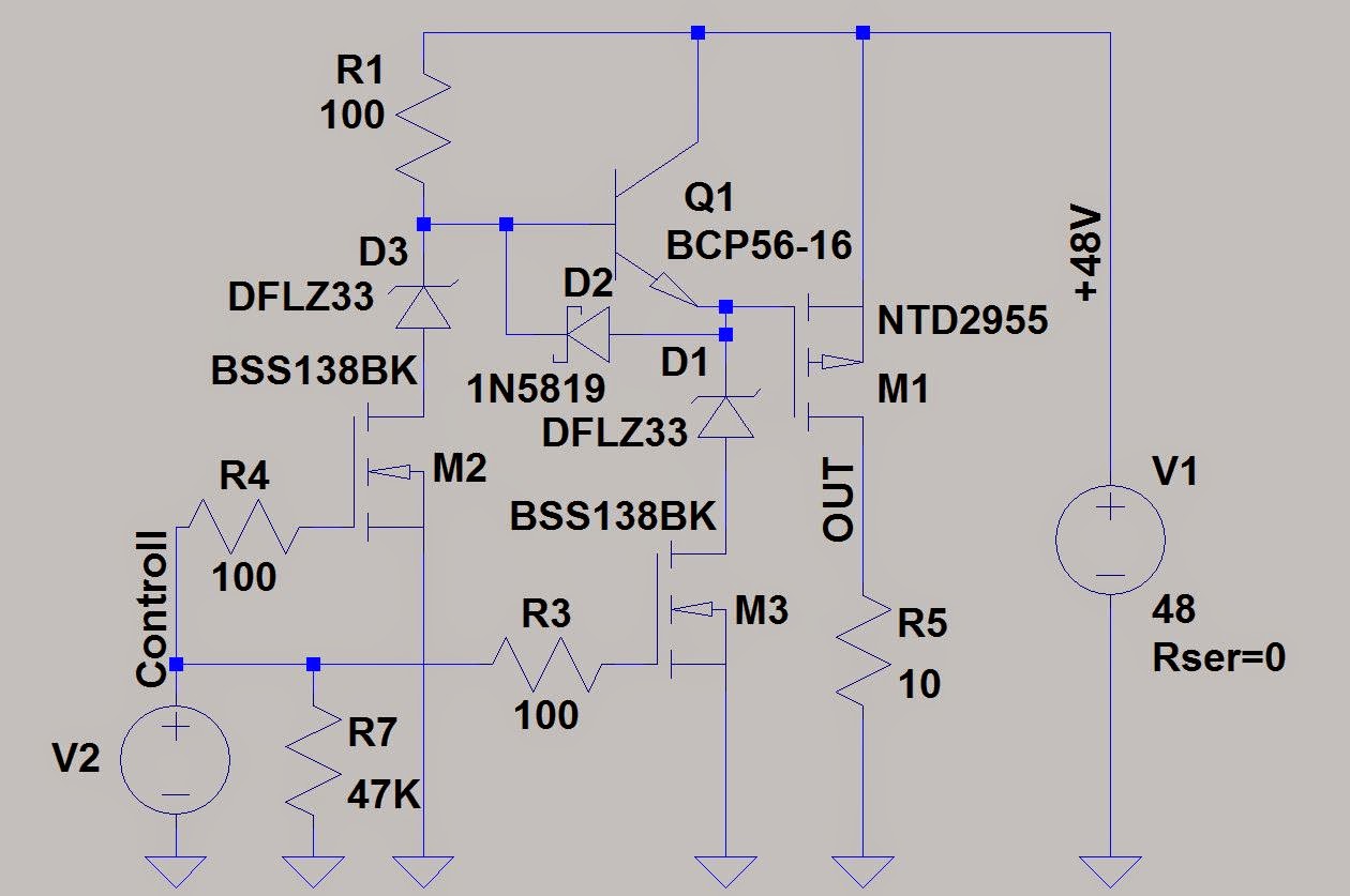
Based on the things above, I designed a little bit different circuit. The reason: I use mostly trough hole components for the home made PCB and switch to SMD when I order the final one.
The schematic

And the PCB design:
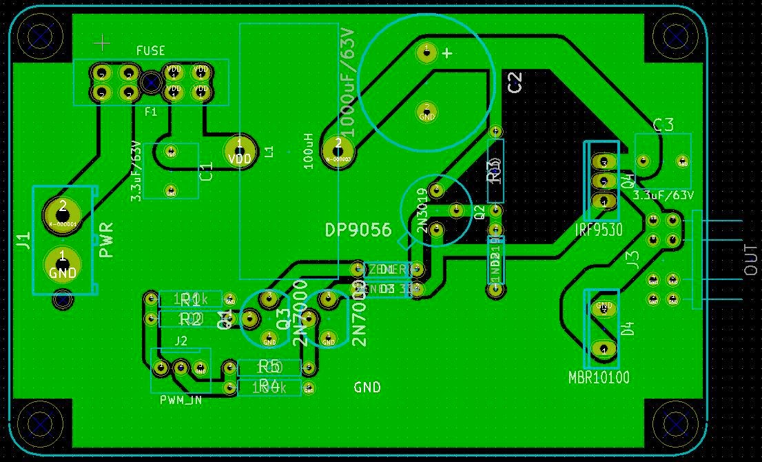
Hopefully I'll be to build it during the weekend.
Discussions
Become a Hackaday.io Member
Create an account to leave a comment. Already have an account? Log In.
Hi Suf
Welcome to the interesting world of power electronics, where all those pesky nanoseconds matter :-)
I'm curious - your PWM_IN connector J2 has 2 inputs. How are these driven?
Additionally, I noticed that you have a little bit of a challenge in the gate drive design: you've used 33V Zeners and the 48V supply rail to provide the -15V Vgs for driving Q4. What happens when the supply is not 48V?
Finally, if you have trouble with D4 getting hot you could move to a synchronous rectification platform (i.e. put a MOSFET where diode D4 is).
jbb
Are you sure? yes | no
Hi jbb,
The two inputs just connected to a single MCU pin for now. I just wanted to keep the opportunity to tweak the switch on and switch off times. Future improvement maybe. :-)
About the Zener. The circuit will be driven from a 48V SMPS, so the 48V is a stabilized input. If I've problem with it, I'll redesign it.
You quite right about the synchronous rectification, I just didn't wanted to complicate the circuit further, or use some drop in integrated controller. If I'll have problem with it, I'll go with a Linear Technology's half bridge controller, what has a boost converter instead of a bootstrap capacitor, to be able achieve 100% duty cycle, and using N Channel MOSFETS.
SUF
Are you sure? yes | no