 SUF
SUFReverse Engineering the CNC control board
During the weekend I was trying (still unsuccessfully, but I don't give up) to get the PWM signal generated by the LinuxCNC out from the parallel interface/stepper driver board.
I would like to achieve without soldering (just to have some challenge).
First of all, about the board.
The machine arrived with a JP-3163B board in it, plus and additional stepper driver for A-axis. Actually, I'd like to keep this board and I want to get as many things I can out of it. The board in question is a version 3.9.
What I found out, that the documentation widely available (and already mentioned by me earlier here), is not completely correspond to my board. Even, if I check the pictures of the boards in sale currently on the AliExpress and eBay, are the same as mine, but the documentation is the other (in fact for the v3.6).
If we are talking about the stepper drivers, and the inputs that are the same, but the additional secondary relay, the spindle drive, the jumpers, or the LED's for the A-axis are totally different.
The only information I can get is the Chinese text from the board itself (not to much).
Part of the 3.6:

And the 3.9:

As you can see the upper has 3 jumpers and the lower has 5. (If you didn't realized, the fifth located next to the parallel connector.
Actually I'm trying to collect as much information about the boards as I can. I found this text somewhere:
现出售的是最新的JP-3163B V3.9版本,增加了延时启动功能和风冷功
能,延时启动是为了更好的保护驱动器不易损坏(风冷为开时,只受Z轴
方向吸合继电器2输出给电磁阀风冷,风冷为关时,做继电器2使用),另
外:本店的手柄只支持以前的V3.7 V3.8 V3.9版本,V3.6版本是不能用
手柄的,请购买手柄的客户买雕刻机手柄时,与店家联系,了解您购买
的板子是否可以配用JP-392Q控制手柄.
Translated (google translate our friends):
Is the sale of the latest JP-3163B V3.9 version, adds delay start function and air-cooled power
Energy, delay start is to better protect the drive easy to damage (air to open, subject only to the Z-axis
Direction of pull solenoid valve relay 2 output to air cooling, air cooling is off, do use relay 2) and the other
Outside: We handle only support the previous version V3.7 V3.8 V3.9, V3.6 version is not used
The handle, the handle when your customers buy buy engraving machine handle, contact with the store, understanding your purchase
Whether the board can be used with JP-392Q control handle.
This is far from perfect, but at least we can see that some changes in the cooling and the delayed start is added somehow to the spindle drive.
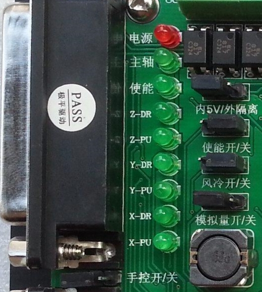
About the LEDs, specially the upper three. On the original board I seen somewhere else English text stating the following:
LED1 (Red) - PWR - Power
LED2 (Green) - A-OR - A-axis direction
LED3 (Green) - A-PU - A-axis step
On my board:
LED1 (Red) - 电源 - Power supply
LED2 (Green) - 主轴 - Spindle (Pin 1 of the parallel port)
LED3 (Green) - 使能 - Enable (Pin 14 of the parallel port)
I also tried to get some information about the jumpers
JP1 - 内 5V / 外隔离 - Within 5V / outer barrier (Internal 5V / External supply ???)
JP2 - 使能开 / 关 - So able to open / close
JP3 - 风冷开 / 关 - Air cooling on / off
JP4 - 模拟量开 / 关 - Analog On / Off (When I switch this of the previous constant 10V disapear from the spindle control)
JP5 - 手控开 / 关 - Manual on / off
Some of the pins of the parallel port are working differently (or has connection to the Spindle control) than it written on the documentation I found:
1 - Spindle On/Off
14 - ??? (Switch On/Off the LED3, but I didn't found any other impact yet)
16 - Realay 2 (It clearly switch on and of the Relay 2, instead of the stated NC)
17 - ??? (Actually I didn't found any impact, it may NC)
This is the current status. I didn't have more time to work on it. I'll definitely continue this, until I'll able to get out the PWM signal in some way.
Front Panel Scematics
I finished the first version of the front panel schematic design. It is in the github repo:
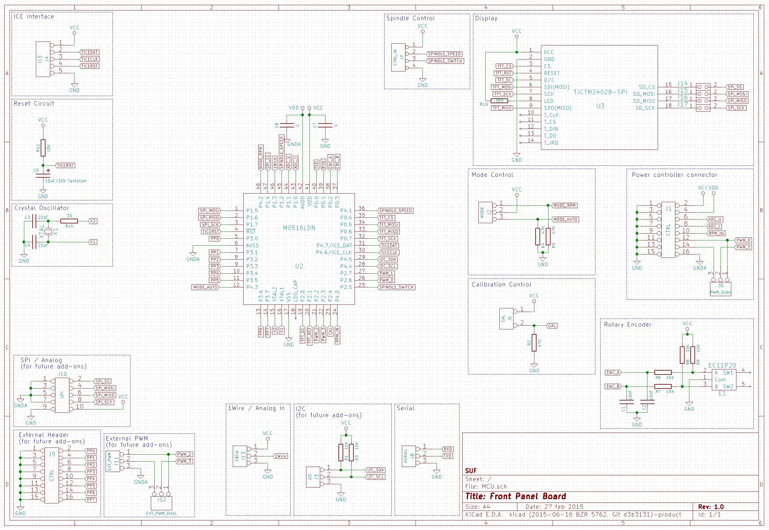
I'd like to add some comments to it:
1. I added lot of external connectors what will not be used but give place for future development
2. The controls are still fuzzy. I may change some hard buttons to a menu based something controllable via the rotary encoder and it's button. This need some tweaks in the hardware also. This means, the schematic will get some slight modifications before the PCB design.
3. The software spindle control has no additional circuit, it is just two pins now on a connector. It will be an add-on board with maybe some protection diodes, level shifting circuit, or optocouplers. It will be based on my finding in the first part of this post. On the other hand, I do this, because this keep the things open to connect different kind of CNC boards.
4. The MCU pins are significantly different from the ones are on the current software implementation (the software will be aligned later). The cause of this, is a misinterpretation of the MCU pins by me. I mixed up the ADxx pins with the AINx pins. The first is external digital parallel bus, what I don't use, and the later is the inputs of the AD converter.
Discussions
Become a Hackaday.io Member
Create an account to leave a comment. Already have an account? Log In.
Very good stuff, thanks for the investigation! I've managed to hook up the A131NBC-8015 VFD to the JP3163B V3.9 controller board and now it is running more or less accurately. Lets say +-500rpm. The PWM pin is 17 and the relay is pin 1. The lowest voltage is about 3.5 v though, but thats fine for me. I'll try to tweak it a bit more tomorrow to see if its possible to go lower.
Are you sure? yes | no
I'm having the same problem as SUF with my JP-3163B v3.9. I have everything working except the spindle 0-10v output. I just sits at 9.81v all the time. I have traced PIN 17 from the parrallel port to the opto on pin number 2 next to the J2 relay. I'm going to hook my scope up to the board and look and see if the PWM is making that far.
After doing some work with a scope, it seems there is pull-up somewhere between pin 17 and the opto. The LPT port on my PC can't pull it down to 0V so it goes back and forth between 5v and 4.5v.
Are you sure? yes | no
SUF, great work, thanks! This post seems to be in fact the only useful documentation on the JP-3163B V3.9.
BTW, I think I have solved the problem with the permanent 10V output: just invert the PWM output pin on the parallel port (it's pin 17) and set the PWM base frequency to 1000Hz. And voila - the spindle is following the output of LinuxCNC!
Thanks again for your great research!
Are you sure? yes | no
Thank you for the information. I'll try this out. I'd like to get a digital output of the LinuxCNC PWM somehow, to be able to measure at my controller board.
Are you sure? yes | no
SUF, Thanks for this project. I have the same JP-3163B V3.9 stepper drive board. At the moment i try find out mach3 settings for this board. But first i need find out parallel port pinouts.
Are you sure? yes | no
If you check the github repo, you will find some pictures, with comments about the board itself. I found them in some Chinese file repository on the net (it wasn't easy to find with the search engines), and added some modifications (marked red) based on my testing.
Are you sure? yes | no
At the moment i find out E-Stop pin on the parallel port is 10 and probe pin is 15
Are you sure? yes | no
I'm a Chinese, here is the translation:
Currently the latest JP-3163B V3.9 version is on sale. Delay start and air cooling is added in this version. Delay start provides better protection to the driver against damage.(When air cooling is on... This is not much readable even in Chinese. Guess it's because I'm not familiar with CNC. The meaning should be "relay#2 controls the air cooling valve when air cooling is enabled, otherwise it's used as relay#2"). The controller handle only support v3.7 v3.8 v3.9. V3.6 is not supported. If you want to buy the handle, contact us to check if your controller board is supported by the JP-392Q handle.
Are you sure? yes | no
Thank you for the correct translation. Unfortunately I still not found what I'm looking for on the board, so the hack solution will come (because I don't want to redesign or replace the board)
Are you sure? yes | no