 SUF
SUFIf I put a diode in series of the motor, the diode will close briefly every time the motor brush step from one commutator segment to the next. This happening because of the sudden change in the magnetic field of the motor. When this change happens the the motor's windings are try to work against the power source, creating a negative current pulse (sorry for my phrasing, I'm not a native English speaker, and my study of physics happened long ago). This can be measured:
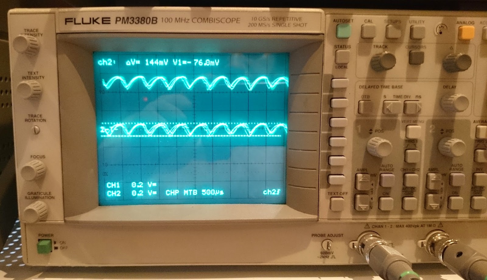
Ok, we can measure the frequency of the above pulse, but I thought, not to feed this signal directly into an MCU, so I did some shaping before.
First of all the signal decoupled with a 1uF capacitor, to keep just the AC part. After this I filtered out the frequencies above the the maximum I can get.
BTW what is the maximum here? The motor has 15000 rpm maximum rotational speed. This ok, but to keep some room, we can start to calculate from 30000 rpm. It should be devided by 60 to get the revolutions per second, and multiply by 12 what is the number of the segments in the commutator. This gives to us 6kHz. Everything above this can be eliminated. The filter in the current circuit has ~7.5kHz:

The filtering is needed because of the switching noise coming from the controller (In the further development this noise will be reduced as much as I can)
The filtered signal is fed into an MCP6002 opamp after transposed to the half supply voltage (2.5V in this case). The opamp is acting as a Schmitt trigger. The hysteresis is set to ~35mV. This is high enough to eliminate the remaining noise but low enough to be able to catch the signal what is around 200mV. At the output of the opamp is a stable square wave what is proportional to the rotational speed of the motor.
Discussions
Become a Hackaday.io Member
Create an account to leave a comment. Already have an account? Log In.