 jaromir.sukuba
As I wrote before, I found this nice application note, and I took the input divider part with 4066 switches, which should serve as input divider of my Progmeter.
I did a quick test on a breadboard, with MCP6041 as voltage follower. Input voltage was generated by laboratory bench power supply, output was measured using normal 3 and 3/4 digit DMM.
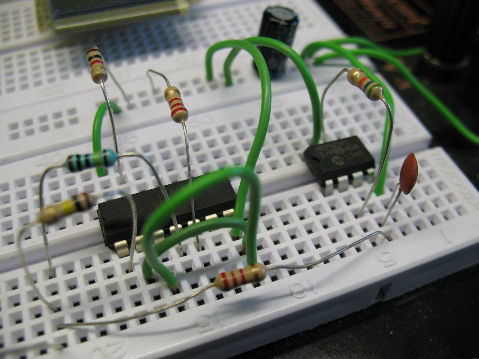 The divider ratios were 101:1, 11:1 and 1:1 (1M as input resistor and 100k or 10k or no resistor as switched divider), the results were quite good, despite the use of poor carbon chinese resistors. Measured dividers were around 103 (101 expected) and 10,95 (11 expected), with slight variation over input voltage range.
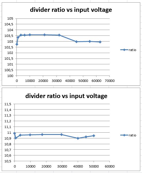
The input voltage is in milivolts. 1:10 divider was tested up to 50V, as the input voltage of opamp can't be higher than 5V; 1:100 was tested up to 63V, as my power supply can't go any higher.
I'm quite satisfied with the results. The strange part near to zero voltage is due to input voltage offset of opamp, the deviation from straightt line is probably due to imprecise voltmeter reading (the differences were a few digits of voltmeter reading).
By the way, for my application is not needed to have precisely 1:10 or 1:100 voltage dividers. As I'm planning to use MCU for data processing, calibration can be done in software, provided the resistors have good stability over temperature and aging. This way I can workaround the need for special values and I can stick with normal E24 or E12 values.
Discussions
Become a Hackaday.io Member
Create an account to leave a comment. Already have an account? Log In.