Close
0%
0%

3RGB image lossless compression format

Tiled CODEC for still and moving pictures based on the 3R compaction algorithm

Similar projects worth following
This project is a study for the design of a new file/stream format, using principles that differ from most existing formats.
The requirements are:
* Few computing and memory resources for decoding
* Asymmetric coding: the encoder does all the hard work, tries features it knows
* Uses only the most basic (and fastest) operations (add/sub, boolean, shift)
* Suitable for still (like PNG or GIF) and moving pictures (like MJPEG)
* No patent or nasty legalese (reference implementation under AGPLv3)
* Great for small CPUs and FPGA
* Support for "don't care" pixels or tiles
* Bytestream made of chunks no more than 1200 bytes each (roughly)

You will find here the details, explanations and specifications for a file format called 3RGB:

  • Supports 24bpp RGB (no palette, only "continuous signals")
  • Multiple levels of features and compression, each level adds a simple feature that the encoder and decoder can accept or ignore.
  • Works with square tiles (8×8 pixels initially, now 4×4)
  • Each tile can be encoded with absolute or relative values (used for delta-pictures in animations)
  • Hierarchical organisation with min/max boundaries of each tile stored in separate 3R-encoded arrays
  • Prediction filter : Paeth or none.
  • scan orders : normal raster (for direct encoding), BitShuffle (when using 3R encoding) or some other pattern for increased locality...
  • Uses the 3R residue compaction algorithm to reduce the size of filtered blocks
  • Uses a Colorspace that is inspired by 3R to reduce the size of the pixels

The requirements so far are not for a solid, stable, monolithic file format like JPEG, GIF or PNG, but rather a toolchest of simple, efficient techniques that can be added progressively to save a bit more bits each time. Depending on the application, one feature can be enabled if it doesn't add much work and yields significant gains. This allows us to design the file/stream format step by step, starting from the most basic and trivial features, providing us with a functioning framework to develop more sophisticated features and evaluate their benefits.


Note that the purposes are compactness and speed of the decoder, rather than high compression ratio. The CODEC tries to grab all the low-hanging fruits to maximise the gains with the least efforts. In particular, the decoder should be as simple as possible and easy to implement, with a small and efficient digital circuit.


Logs:
1. Colorspace
2. Chunking
3. Recursive definition of a 2D signal
4. Tiling
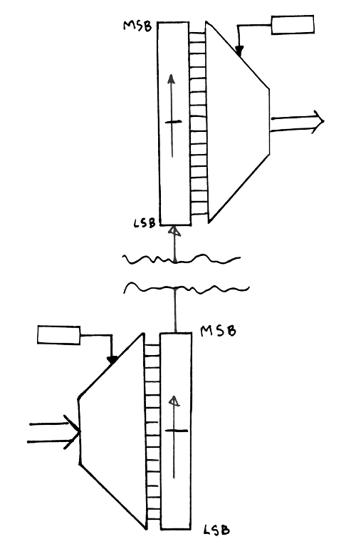
5. Phase-out encoder/decoder
6. Another case of combinatorial dilemma
7. Colorspace decomposition (episode 2: the big swap)
8. Basic algorithm for one block
9. Design of the phase-out code
10. Extension to alpha channel
11. Phase-out in C
12. Block sizes and other considerations...

.

test-phaseout.c

Exercises phaseout.c, run for sanity checks.

text/x-csrc - 3.07 kB - 07/04/2017 at 08:08

Download

raw2sa_01_bytes.OK.c

dumb test for phaseout.c

x-csrc - 1.57 kB - 06/08/2017 at 11:16

Download

phaseout.c

encoding and decoding functions for phaseout bitstreams (version 20170704)

text/x-csrc - 3.39 kB - 07/04/2017 at 08:06

Download

x-csrc - 8.88 kB - 06/06/2017 at 06:08

Download

bitstream_dev.c

a development version with a lot of checks and messages, exercises over a block a million times

x-csrc - 6.90 kB - 06/05/2017 at 14:00

Download

View all 9 files

  • Block sizes and other considerations...

    Yann Guidon / YGDES08/14/2017 at 11:47 0 comments

    Right now I'm wondering if the benefits of a 4×4 pixels tile justify changing the format definition, particularly for high-entropy blocks. Or maybe dynamically switching from 4×4 (high entropy) and 16×16 tiles (low entropy). Which adds one flag bit in front of a non-leaf tile.

    It's the old "bad apple" syndrome : one outlying sample can wreck the compression ratio. The majority of the samples shouldn't "pay" for a single one, the goal is to prevent this sample from spilling over the whole dataset...

    A smaller block also helps with code optimisation because some loops can be unrolled nicely.

    Now that I think of it : merging tiles into a larger one IS possible. More on this later...

    Packet size : limited to 1024 bits so the size field uses only 10 bits. Code 0000000000 means 1024. This is simpler than adding +1. Empty packets make no sense, right ?

    Progressive encoding and decoding : this requires significantly more memory and temporary storage, but is more resilient. And during decoding, if a sub-block is altered, the whole block can be filled with the average of the min and max values... 


    20171028 : how to save one flag bit ? In the parent tile, if the limits are identical (or sufficiently close) for 2×2 tiles or 4×4 tiles, then the subtiles can switch sizes to 8×8 or 16×16. No need to deal with an explicit space-wasting flag...

  • Phase-out in C

    Yann Guidon / YGDES06/05/2017 at 15:13 0 comments

    The C version of the phase-out is at bitstream_dev.c and it sounds promising. A new version is available as phaseout.c along with some testbench code.

    This is only a development version, cluttered with #ifdef and sanity checks but the final versions wil be much more compact and based on macros, sprinkled over the concerned functions (not even inlined).

    One interesting characteristic is the size of the shift register : I use 64 bits in this version. It could be 32 bits (as in the hardware implementation) but there is one benefit : you can shove up to 32 bits without having to check for an overflow, whatever the original position (because the last sequence has shifted the high half out already).

    For the encoder or decoder, this means that you can process up to 4 bytes, or a whole pixel, without testing if you need to read or write a word to/from memory. The saving in code size and in speed is not negligible and at least it exploits the recent processors.

    Unfortunately the A53 cores at the heart of the Raspberry Pi 3 are not running in 64 bits mode, we'll see if the Neon extension can be used...

    But at least, encoding will not be dog-slow because of this.

    Todo :

    1. create a merged version of send_phaseout and receive_phaseout that does not call the bit insertion/extraction routines (an inlined, streamlined version)
      (20170704: DONE)
    2. split the functions into various macros.

  • Extension to alpha channel

    Yann Guidon / YGDES06/05/2017 at 00:33 0 comments

    The previously described algorithms apply equally for 4-channel pictures, using RGBA for example. The color transform looks even more like the 3R algorithm with 4 leaves...

  • Design of the phase-out code

    Yann Guidon / YGDES06/03/2017 at 19:02 0 comments

    The phase-in code (or truncated binary code) is significantly better than the plain binary code because it can remove one bit from a number in certain cases.

    http://ygdes.com/3r/ has shown that a modified version, the phase-out code, is (in average) slightly better than phase-in code. It is not always the best because it depends on the provided data. However, we don't care much about reducing the size of numbers that are already small : the large numbers are those that must be reduced.

    The early tests used a simple transform (n = lim - n) to reuse the existing phase-in code. The optimised version must use a leaner, more direct and less serial algorithm, which can then be implemented in logic gates. I had to come up with a suitable algorithm, which is:

    Parameters:
    k bits maximum,
    mask = (1<<k) - 1;
    mask>>1 ≤ lim ≤ mask;
    n ≤ lim
    if ( n > (((lim<<1) &mask) |1 )) { k--; n = n+(mask>>1) -lim; } send_bits (n, k);

    This is quite similar to the code for phase-in presented by Wikipedia (edited for coherence):

    u = (1 << k) - lim;
    if (n < u) send_bits(n,   k-1); 
          else send_bits(n+u, k  );
    

    There are some very interesting nuances however:

    1. The expression (((lim<<1) &mask) |1 ) amounts to a rotation of lim, it is very easy to design/wire as a digital circuit.
    2. The expression n+(mask>>1) -lim has various expressions that are easier to wire as digital circuits, such as n- (lim & mask>>1) +1, which amounts to a simple subtraction with one masked operand (and the mask's LSB is dropped). The +1 can be wired as a carry-in set to 1, which can be also optimised out in logic.
    3. Both expressions above can be computed in parallel because they are independent. As a digital circuit, the results n and k are selected with a MUX controlled by the comparison's result. As a program, in a superscalar processor, the various values are computed speculatively and affected with a predicate.

    I am more concerned by the computational cost and latency in hardware than software, and by the decoding than the coding.


    Speaking of decoding, there is the requirement to play nicely with the bitstream extraction circuit: call the function receive_bits() only once, but how do we know how many bits to get, since it's a variable length code ?

    If the function is called with the shortest size in argument, it must be called later to complete the missing bit. This takes more time, but there is no risk to overflow the bitstream when it reaches the end.

    So the fast solution is to over-request bits: if the received number uses fewer bits than requested, the bit pointer can be re-adjusted before the next cycle. This solves the question of speed but leaves us with a new probem: what happens when the stream ends on a word boundary with a short code ?

    It is easy to know when the bitstream ends and almost as easy to not read one more word beyond the end. The stream reader could return any value because it will not be used. It can be zero, all ones, or the last value.

    However the register must be shifted because the shifter can't shift by -1.

    The file test-phase-out.html demonstrates the algorithm with JavaScript.

    There's a few details that I had to iron out but now it works: exercise-phase-out.html

    • Actually, decoding past the last word should return 0 : returning 1 creates all kinds of problems...
    • the decoding is almost like encoding, but I forgot to integrate the fact that one LSB should be removed:
        val=receive_bits(k);
        if (val > (((lim<<1) &mask) |1 )) {
          val = ((val>>1)+lim)-(mask>>1);
          rcvReg.offset++; // re-increment the bit counter
        }

    Apart from that, it works like a charm.


    20170704

    Some code optimisations give the simplified result for encoding:

      uint32_t k=0, l=lim, mask;
    
      if (lim) {
        // generate mask from lim
        if (l & ~255) { k =8; l=lim>>8; }
        if (l & ~ 15) { k+=4; l>>=4; }
        if (l & ~  3) { k+=2; l>>=2; }
        if (l & ~  1) { k+=1; l>>=1; }
        mask=(1<<k)-1;
    
        if ( (val>>1) > (lim & mask) )
          val+=mask-lim;
        else
          k++;
    
    OTOH decoding is a bit more hairy...
      uint32_t
        val=0,   // default value...
    Read more »

  • Basic algorithm for one block

    Yann Guidon / YGDES06/01/2017 at 04:11 0 comments

    Greyscale encoding is less interesting than RGB because there is less potential for compression. So far, one 8×8 RGB block is encoded with these steps:

    1. Get the min/max of each component:
      // the input data for one 8×8 block:
      var R=Array(64),
          G=Array(64),
          B=Array(64);
      // scan:
      var
        minR=R[O],
        minG=G[O],
        minB=B[O],
        maxR=minR,
        maxG=minG,
        maxB=minB;
      for (var i=1; i<64; i++) {
        var t=R[i],
            u=G[i],
            v=B[i];
        if (minR > t) minR = t;
        if (maxR < t) maxR = t;
        if (minG > u) minG = t;
        if (maxG < u) maxG = t;
        if (minB > v) minB = t;
        if (maxB < v) maxB = t;
      }
      	
    2. Send min/max|R/G/B/ right away, or store them somewhere else for further processing. Here it's the case of direct transmission: min is encoded right away as a byte, max is encoded with phase-out code because it is in the range [min..255]
      send_byte(minR);
      send_byte(minG);
      send_byte(minB);
      maxR -= minR,
      maxG -= minG;
      maxB -= minB;
      send_phaseout(maxR, 255-minR);
      send_phaseout(maxG, 255-minG);
      send_phaseout(maxB, 255-minB);
      	
      In a more elaborate version, the minX and maxX are collected in another 8×8 array for further processing and compaction.
    3. This step is just for the formal definition but it will be merged with other steps: remove the minX offset from the respective blocks
      for (var i=0; i<64; i++) {
        R[i] -= minR,
        G[i] -= minG,
        B[i] -= minB;
      }
      // Prediction filter can be applied here too
      	
      Now, minX is out out of the way. We'll bother only about the amplitudes after this point.
    4. Sort the component in order of max. amplitude
      var Cmax, Cmed, Cmin;
      var maxMax, maxMed, maxMin;
      
        Cmed =    G; // speculative assignation
      maxMed = maxG; // (used by two cases)
      // possible cases: BGR, BRG, GBR, GRB, RBG, RGB
      if (maxR > maxG) {
      // possible cases: BRG, RBG, RGB
          Cmin =    G; // speculative assignation
        maxMin = maxG; // (used by two cases)
        if (maxR > maxB) {
      // possible cases: RBG, RGB
            Cmax =    R;
          maxMax = maxR;
          if (maxG > maxB) {
      // actual case: RGB
              Cmin =    B;
            maxMin = maxB;
          } else {
      // actual case:  RBG
      //  (can goto to case GBR)
              Cmed =    B;
            maxMed = maxB;
          }
        } else {
      // actual case: BRG
            Cmax =    B;
          maxMax = maxB;
            Cmed =     R;
          maxMed =  maxR;
        }
      } else {
      // possible cases: BGR, GBR, GRB
          Cmin =    R; // speculative assignation
        maxMin = maxR; // (used by two cases)
        if (maxG > maxB) {
          // possible cases: GRB, GBR
            Cmax =    G;
          maxMax = maxG;
          if (maxR > maxB) {
      // actual case: GRB
              Cmin =    B;
            maxMin = maxB;
              Cmed =    R;
            maxMed = maxR;
          } else {
      // actual case:  GBR
              Cmed =    B;
            maxMed = maxB;
          }
        } else {
      // actual case: BGR
            Cmax =    B;
          maxMax = maxB;
        }
      }
      	
      This block of code might look large and scary but it's optimised for fast execution: at most 5 assignations and 3 tests.
      (note that Cmin, Cmed and Cmax are just "pointers", or can be implemented as different types of circuits)
    5. Implement the nested color transformations σα( σα(Cmax, Cmed), Cmin)
      1. σα(Cmax, Cmed) generates
        • the sum S1=Cmax+Cmed, with limit L1=maxMax+maxMed,
        • the reversed data A1 (depending on Cmed), with limit L2≤maxMed
        A1 and L2 can be used (almost) immediately or they can be stored in two new arrays for further compaction with 3R.
      2. σα(S1, Cmin) generates
        • the sum S2=S1+Cmin, with limit L3=L1+maxMin,
        • the reversed data A2 (depending on Cmin), with limit L4≤maxMin
        Again, A2 and L4 can be used (almost) immediately or they can be stored in two new arrays for further compaction with 3R.
    6. For the direct transmission, send the computed values in reverse order of the previous part (to allow decompression)
      for (var i=0; i<64; i++) {
          // (Compute step 5 here)
        send_phaseout(S2, L3); // Sum
        send_phaseout(A2, L4); // Cmin
        send_phaseout(A1, L2); // Cmed
      }
      	
      Notice that certain values do not change within a block (L1, L3 and some parameters of σα), so they can be precomputed before the loop's body. The others require additional temporary storage (S1, A1, L2, A2, L4).
    7. Steps 5 and 6 can also be computed in parallel with...
    Read more »

  • Colorspace decomposition (episode 2: the big swap)

    Yann Guidon / YGDES06/01/2017 at 01:19 0 comments

    After having progressed on the other fronts, I return to the colorspace decomposition where I'm now addressing another "low hanging fruit" : that is, some way to gain a bit more space with relatively little effort, and without risk of expansion. I guess the average gain would be in the 10 to 20% range but this depends a lot on the data. This is a small gain but not negligible and the required effort is modest : it's a small permutation based on already known data.

    As mentioned before, the 3RGB encoding pipeline breaks the image in 8×8 tiles and the first step is to compute the min and max values of each block, in parallel, for the individual R, G & B components.

    Then, the 3 blocks (R,G,B) are transformed to the new colorspace by applying two nested σα transforms. Since we know the min and max values of each block, we can apply the generalised algorithm (see Extension to unequal boundaries) which swaps the operands: the smallest range is output after the sum.

    We can go a bit further and pre-swap the block pointers: this simple step takes the swap out of the inner loop, which runs faster.

    There are 6 permutations for RGB:

    1. B G R
    2. B R G
    3. G B R
    4. G R B
    5. R B G
    6. R G B

    A little bubble sort would be enough but we don't need to go so far : two of the components are reproduced verbatim (at worst) so we just need to find the largest limit and map it to the intermediary sum (which is not directly transmitted)

    Another parameter comes into play: the second σα transform applies to the sum of two components, so we could evaluate

    1. B + G
    2. B + R
    3. R + G

    but if we already know, for example, that B is the largest value, then B+G > R and B+R > G.

    This leaves us with only 3 practical combinations:

    1. σα( σα(B, G), R)
    2. σα( σα(G, R), B)
    3. σα( σα(R, B), G)

    with the function σα(a,b) returning the sum a+b, and range(a)>range(b) (the modified b is sent on the bitstream).

    Does the order of the two smaller ranges matter ? I think it's better to have the highest difference possible between the operands, so the general formula would be

    σα( σα(max, med), min)


    See the rest of the algorithm at Basic algorithm for one block

  • Another case of combinatorial dilemma

    Yann Guidon / YGDES05/30/2017 at 23:37 0 comments

    As one block of 64 number is scanned, the min and max values are computed. The min value is subtracted from all the sample, as well as from max.

    This implies that

    • at least one sample will have the value min
    • at least one sample will have the value max

    Wouldn't it be cool if we could use these informations to save more space ?

    Let's take the example of max, which in our case can be anywhere from 0 to 765 (up to 10 bits for luma). We have 64 values, so the index fits in 6 bits. The gain can be negative or positive:

    • in the best case, where max uses 9 bits (due to phase-out, instead of 10 with phase-in), we gain 9-6=3 bits, for a block of 64 values (that's really insignificant)
    • in the worst case (max<6) up to 6 bits are lost (though max==0 is a condition to not decode the block, which would be empty)

    The same goes with min, though min usually encodes in less bits than max.

    In our case, the special values can not be represented in an efficient way. We have to count on using 3R for increased compaction and there is some inherent redundancy that can't be removed. And the above case only addresses the assumption that there is only one value equal to min and one that is equal to max. How do you manage the case where more than one value is used ?


    Note for later:

    With fewer values of higher amplitude (like, chunks of 16× 16-bits numbers for example), the "min/max index" uses 8 bits and can save up to 24 bits so this is a valuable trick for sound compression.


    Part of the answer is the use of recursive σα transforms because the very high values are reduced to few bits, like the very low values.

    Another approach is to encode the max value with a different code, such as 1 (0 is reserved for min). The other values are incremented: 1 becomes 2 etc. However this might not be as beneficial because

    • There is no direct gain with simple use of phase-in/out only
    • It could interfere with the behaviour of 3R and σα.

  • Phase-out encoder/decoder

    Yann Guidon / YGDES05/30/2017 at 06:53 0 comments

    This log continues after 11. Design of the bit extraction circuit has stopped.

    The last log 4. Tiling explains why the tiles are limited to 8×8, this keeps the highest luma values under 64K. We can work with a 32-bits processor

    We also know that the direction of the shift must be reversed (in MSB order) to prevent nasty corner cases encountered in the original code.

    The chosen approach is:

    • rough (8- and 16-bits granularity) on the "stream" side (the network or filesystem)
    • fine granularity (up to 16 bits shifted by 0-31 bits) for the encoder/decoder side

    It should be both easy to implement with code and logic gates, in particular the byte/word insertion and extraction can be limited to a single location, which simplifies some of the circuitry (but adds one cycle of delay for the very first cycle).

    The source and sink sides can work with a 16-bits wide shift register that can shift up to 32 positions (that's 4 MUX2 layers of 16 bits, at most 128 gates)

    The type of truncated binary code is "phase-out", which is reversed phase-in where the lower value range uses one more bit.

    The encoder starts to put the first VLC at the "top" of the shift register. More VLC are added, at decreasing indices, until at least 16 bits have been written to the shift register. The top half of the register is then sent to the receiver, then the lower half is copied to the top half.

    At the receiving end, the shift register is filled with the 2 first 16-bits words, then starts to read the bit fields starting from the MSB. When more than 16 bits have been read, the shift register is shifted by 16 bits (the lower half overwrites the higher half) then the lower half is read from the stream of words.


    20170602:

    Working with a given word size, I realise that one bit can be saved.

    For 16-bits words, the register needs only 31 bits because the word can only be shifted by 15, the 16th is no-shift.

    So the counter goes from 31 (shift register empty) down to 0 ("flush the high word, man !") and the lower half has only 15 bits instead of 16.

    In hardware, the shift counter might even be stored as only 4 bits, while the subtraction would use 5 bits to detect the overflow (which triggers the emission of the word), just like a pulse-density (sigma-delta) modulator...


    20170603:

    test-bitstream.html contains a simple test for the encoder and decoder, without the phase-out part.

    I must design the phase-out code then rewrite the routines in C.

  • Tiling

    Yann Guidon / YGDES05/30/2017 at 06:10 0 comments

    There is this old question of the appropriate size of the tiles, usually this is a dilemma between 16×16 and 8×8.

    The first thing to consider is that, since 3RGB doesn't actually model the signal, there is little need for large tiles because a stray "very high pixel" will affect 4× more values with 16×16, than 8×8. The "lone wolf" has more deleterious effect with a large tile.

    A smaller tile makes the stream more resilient in case of transmission/storage error. The whole tile can be discarded with 4× less visual effect.

    A smaller tile fits easily in "BlockSRAM" memories of FPGA. Or more tiles in a BlockSRAM. The latest MicroSemi FPGA (Igloo2, SmartFusion2 and PolarFire) even have perfectly sized 2R1W register blocks (4 entries, with 12 bits of PolarFire).

    The major factor however concerns the design of the bit serialiser/shifter, the width depends on the largest value that needs to be represented. The worst case is with the luma blocks that use 3R:

    • For 8×8: 64 values of max 765 = 48960 (fits well in 16 bits)
    • For 16×16: 256 values of max 765 = 195840 (requires 18 bits)

    The obvious problem is that handling 18-bits values with a 32-bits processor is more complicated than 16 bits, because 32/2<=18 and

    • the shift register can process up to 1×16-bits word per cycle, whereas 18-bits words reduce the granularity to bytes,
    • up to 3 cycles (1 per byte) might be required to make room for a new word in the shifter's barrel, but the 16-bit shifter can make room immediately or in parallel, the bandwidth is much better

    So the granularity is settled to 8×8 pixels per tile...

  • Recursive definition of a 2D signal

    Yann Guidon / YGDES05/26/2017 at 06:07 0 comments

    Everybody today is familiar with the representation of a picture, as a two-dimensional array of discrete values. 3RGB achieves some compression by adding recursively higher orders of granularity, where groups of pixels are summarised by their range, as a pair of values that represent the minimal value of pixel(s) in the group, as well as the largest value (relative to the minimum value).

    The whole picture, made of discrete and inherently bounded values (usually from 0 to 255), is condensed in several step down to a pair of {min, amplitude} values. This is a significant departure from the classic frequency analysis transforms (DCT, wavelets...) where the "root value" is usually a single DC component.

    Compression is possible because the amplitude is related to the minimum through the inherent boundaries of the input sample: minimum + amplitude max.bound

    In other words, amplitude max.bound - minimum

    Given these two informations about a block of samples, each sample can be represented with less bits, for example with a bitstream of truncated binary codes (also called phase-i or economy code) or with 3R (which has the added advantage of also compacting closely related value tighter).

    Once the decoder receives the "root" pair {min,amp}, it can decode a first block that contain the array for the first/highest level of min values. This array can be encoded as a simple concatenation of phase-in codes or with 3R for better compaction. At the same time, the first decode stage can generate the boundaries for the following array of amplitudes. Each individual min value will implicitly limit the range of the respective amplitude.

    At the lowest level, each picture tile will have its minimum and amplitude values provided by the next higher level of arrays, and only an array of amplitudes is encoded. The only special case concerns the delta pictures: the amplitude of the tile is multiplied by 2 (unless it's 0, which means "nothing to encode here, just fill the tile with a constant color") and the LSB is a flag that selects between absolute or relative coding (the values are relative to the precedent value of the tile).

View all 12 project logs

Enjoy this project?

Share

Discussions

Simon Merrett wrote 06/01/2017 at 17:27 point

Yann, I'm way over my head just reading the intro for this project but are there opportunities to assist e.g. OpenCV in this format, so that it wouldn't necessarily require full decoding to analyse a file for the features a CV program is looking for?

  Are you sure? yes | no

Yann Guidon / YGDES wrote 06/01/2017 at 21:01 point

Hi Simon,

I am not sure to understand the details of the implications, but since  I intend it to be a recursive format (one root 8×8 block, providing info on 64× 8×8 blocks and so on) yes it could be possible to perform something like motion detection, to spot zones of interest for further analysis.

But so far I have different priorities, I need to losslessly halve the room taken by images for videos...

  Are you sure? yes | no

Simon Merrett wrote 06/01/2017 at 21:57 point

Good luck! 

  Are you sure? yes | no

Similar Projects

Does this project spark your interest?

Become a member to follow this project and never miss any updates